Barco RACKMOUNT DX-700 User Manual
Page 2
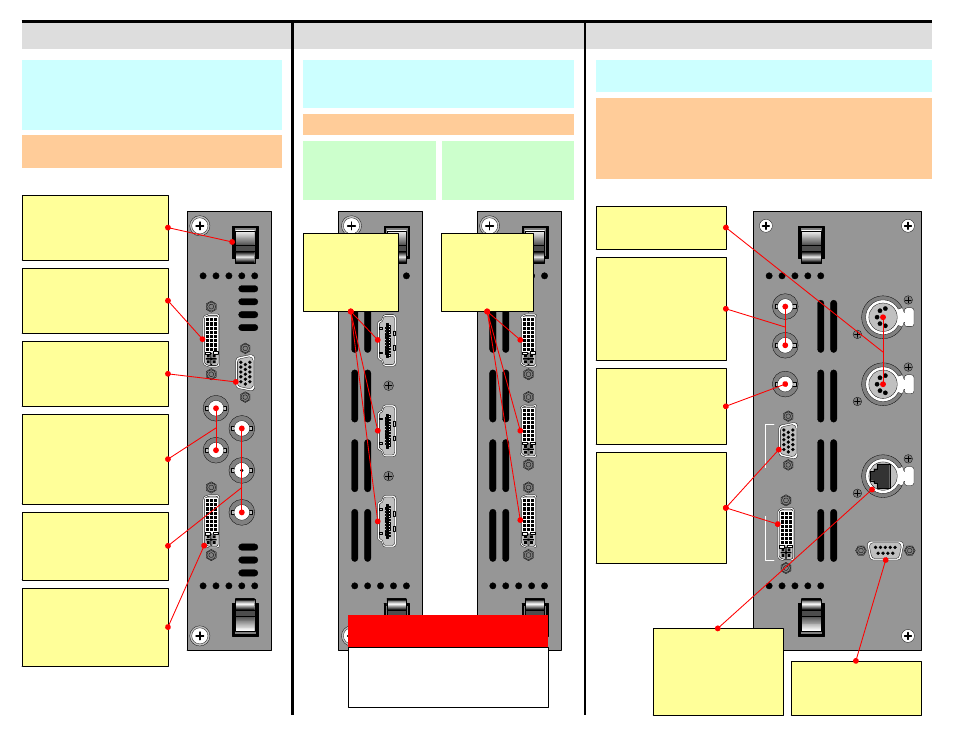
RGBHV Monitor Out
DVI Monitor Out
Use the Monitor Output
Menu to set resolution and
video source. Both outputs
show the same video.
Expansion Lock Out
For external stacking
configurations, provides
sync and communications
to additional DX-700s.
System Module
Output Modules
Input Module
EXP OUT
D
V
I / E
X
P I
N
RGB
H
V
1
-H
D
/S
D
I -2
Y /
C
O
MP
C /
Pb
Pr
Latches
Used for precise insertion and
removal. See the “Module
Insertion and Removal” section.
Expansion Out
Connects input modules for
external and cross-bank
stacking configurations only.
RGBHV Input
Accepts RGBHV inputs up to
QXGA (2048 x 1536), with a
max. 240 MHz pixel clock.
HD / SDI Input
Accepts:
• 2 x SDI
• 2 x HD-SDI
• 1 x SDI and 1 x HD-SDI
• 1 x Dual HD-SDI
DX-700 Input Modules provide the system’s input,
scaling, and mixing functions. Within each module, the
input source is selected from among the various input
connectors and scaled to the required size and position
in the final display.
Component Input
Accepts Composite, S-Video
and Component. See the
“Format Connection Table.”
DVI / Expansion Input
Accepts single or dual DVI
inputs, with resolutions up to
QXGA (2048 x 1536) with a
max. 240 MHz pixel clock.
Each module provides three outputs, which can drive one
(or more) attached displays from any portion of a selected
source image.
LED
OU
T 1
LE
D O
U
T 2
LED
OU
T 3
LED O
U
T 1
LED
OU
T 2
LED
OU
T 3
LED Outputs
Three DVI-I type
connectors are
provided for DVI
outputs.
LED Outputs
Three HDMI-type
connectors are
provided for NNI
outputs.
WARNING
Output Module connectors use proprietary
signals and pinouts. Do not connect the
outputs to anything other than the inputs of
Barco LED tiles.
• Use the Setup Wizard to configure outputs and groups.
• Use the Input Wizard to configure inputs.
• Use the Input Management Menu to fine tune inputs.
DI
AGNO
STIC
ETHER
N
ET
DM
X THR
U
DM
X I
N
V I
N
H
/ C
S
I
N
LOCK
MO
N
IT
O
R
GEN
L
OCK
EX
P
The System module provides connections for Ethernet, synchronization
(genlock), monitoring, DMX and diagnostics.
Under the DX-700 Management Menu:
• Use the Ethernet Menu to configure Ethernet parameters.
• Use the Monitor Setup Menu to set monitor output parameters, test patterns, and
the monitor’s video source.
• Use the Genlock Menu to set the master sync source, and individual bank
genlock sources.
Genlock Inputs
•
Single: connect
composite sync or
black burst to H/CS IN.
•
Separate: connect H
and V sync to H/CS IN
and V IN.
DMX Control
Currently not implemented.
Ethernet
100BaseT connection for
Director Toolset
communications. Use the
Ethernet Menu to set
parameters.
Diagnostic Port
For factory and technical
support use only.
DVI Output Module
Runs legacy LEDs. Each
output is limited to
800 x 600 pixels.
NNI Output Module
Runs next generation LEDs.
Each output is limited to
1024 x 768 pixels.