Top control panel – Bowens QUAD BW-7620 User Manual
Page 4
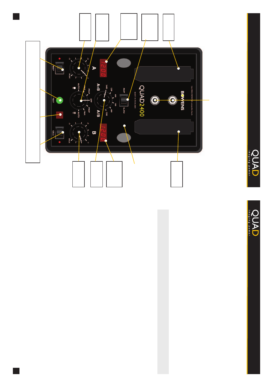
Control Panel Guide
W
arnings Signs and
T
roubleshooting
4
9
If the unit appears to have developed a problem, first establish that it is a genuine internal problem and
not a case of normal operation such as overheating. Carry out the following checks to eliminate any
external causes. If no obvious problem can be found and replacement of the modelling lamp, flash tube
or flash head fuse does not eliminate the problem, then it is likely that an internal problem has
developed.
Always return the unit to an authorized service centre if a problem is suspected after these
checks. UNDER NO CIRCUMST
ANCES SHOULD
YOU
A
TTEMPT
ANY
REP
AIR
YOURSELF
.
• Overheat W
arning
The power pack is fitted with a thermostatically controlled fan, but under extreme conditions of use the
power pack may still overheat, even with the fan running. Flashing less frequently and/or using the
Slow Charge Mode will normally help prevent this from happening.
Overheat protection is provided to inhibit charging until the unit has cooled suf
ficiently to operate
normally
.
The Power Level Displays will flash “Overheat” warning while the overheat condition exists.
NOTE:
The overheat condition remains until the power pack reaches a safe operating temperature or
the unit is turned of
f and allowed to cool.
• Control Panel Does Not Light Up
If the Control Panel does not light up when the unit is switched on, first check the
AC power-cord
connections and check to make sure the
AC outlet is working. Under exceptional conditions of use or
component failure, the Internal Fuse may blow
.
This is designed to protect the unit. Report the problem
to your local service agent. DO NOT
A
TTEMPT
T
O
LOCA
TE
AND REPLACE
THE INTERNAL
FUSE
YOURSELF
.
• Control Panel Lights Up But Ready Indicator Does Not Light Up
If this happens, first confirm that the
AC-line voltage is adequate and within the prescribed limits.
Confirm that the Flash
Thermal Reset Button on the Rear Panel is pushed in. Under exceptional
conditions of use, this may trip. Switch the unit of
f, wait a minute, push the button in and then switch
power on again.
• Modelling Lamps
Are Not W
orking
If all of the modelling lamps are not working, first check to see if the Modelling
Thermal Reset Button
on the Rear Panel is out. If this is the case, DO NOT
RESET
IT
until you have checked the head(s) for
blown bulbs and/or fuses.
• Power Pack T
riggers Erratically
Check to see if the power pack is being triggered by another flash source by turning the photocell of
f.
T
op Control Panel
Sync Sockets
Head
Socket ‘A
’
Head
Socket ‘B’
Fast/Slow
Switch
(
Under Handle)
Carry Handle
Channel A
Power Level
Display
Channel B
Power Level
Display
Overall Power
Selector
Modelling
Mode Selector
Channel A
V
ariator
Channel B
V
ariator
Audio Switch
and LED
Photocell
Switch and LED
T
est Button and
Ready Indicator
Photocell
Window
www
.bowens.co.uk
www
.bowens.co.uk