7 programming – BEA 10MATRIX User Manual
Page 3
75.1046.04 EN 20080505
Page 3 of 5
7 Programming
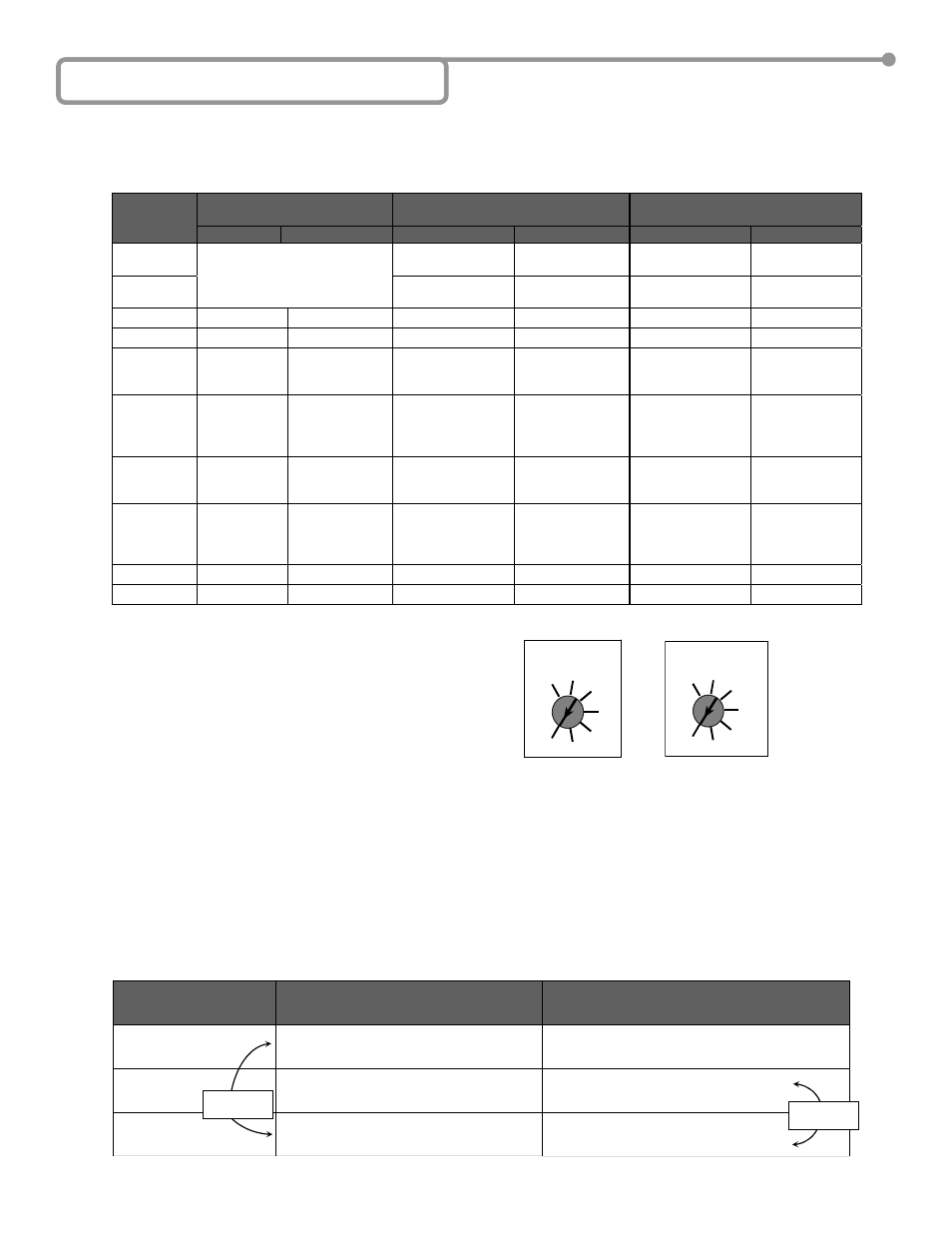
I. THE 3 CONFIGURATIONS
A. Configuration A: Single Loop Detector (MATRIX-S)
B. Configuration B: Dual Loop Detector in Independent Mode with Dipswitch #10 OFF (MATRIX-D)
C. Configuration C: Dual Loop Detector in Combined Mode with Dipswitch #10 ON (MATRIX-D)
II. POTENTIOMETERS
A Potentiometer for Adjustment of the Maximum Duration of a
Presence Detection: from 1 min to Infinity (See PRESENCE TIME)
A Potentiometer for Adjustment of the Linear Sensitivity ( f)
for the Loop A: from 0.005% to 0.5% (See SENSITIVITY)
A Potentiometer for Adjustment of the Linear Sensitivity ( f)
for the Loop B: from 0.005% to 0.5% (See SENSITIVITY)
III. RELAY CONFIGURATION (DIPSWITCH #3)
A 10 position dip switch is located on the front of the Matrix single detector. Dip switch 3, 5, 6, 7 and 8 configure the relay, while dip switch 9
controls the duration of the pulse when the Matrix is configured for pulse operation, (as opposed to presence). Configurations are as follows:
DIPSWITCH 3:
OFF= FAIL-SECURE MODE Relay is NOT energized when power is applied. Relay is energized upon detection only. In this mode, the NO
circuit is open, and the NC circuit is closed. Thus, if a closed circuit is required upon detection, one must use the NO and COM terminals
since they would close upon detection. When the Matrix is NOT powered, it is in the same state as it would be for non-detection.
ON = FAIL-SAFE MODE Relay is energized as soon as power is applied and de-energizes upon detection or power loss. In this mode, upon
powering the detector, the NO circuit becomes closed, and the NC circuit becomes open. Thus, if a closed circuit is required upon detection,
one must use the NC and COM terminals, since they would now be OPEN during non-detection, and would close upon detection. When the
Matrix is NOT powered, it is in the same state as it would be for detection.
Configuration A
Single loop
Configuration B
Dual loop in independent mode
Configuration C
Dual loop in combined mode
Dip Switch
OFF
ON
OFF
ON
OFF
ON
DS#1
High (loop A)
Low (loop A)
[High –30%]
High (loop A)
Low (loop A)
[High –30%]
DS#2
See next table
High (loop B)
Low (loop B)
[High –30%]
High (loop B)
Low (loop B)
[High –30%]
DS#3
Active mode
Passive mode
Active mode
Passive mode
Active mode
Passive mode
DS#4
ASB OFF
ASB ON
ASB OFF
ASB ON
ASB OFF
ASB ON
DS#5
Relay A :
Presence on
loop A
Relay A :
Pulse on loop
Relay A :
Presence on loop A
Relay A :
Pulse on loop A
Not used
Not used
DS#6
Relay A :
Pulse on loop
A
entry
Relay A :
Pulse on loop A
exit
Relay A :
Pulse on loop A
entry
Relay A :
Pulse on loop A
Exit
Relay B :
Non-Directional
mode
Relay B:
Directional AB
mode
DS#7
Relay B :
Presence on
loop A
Relay B :
Pulse on loop A
Relay B :
Presence on loop B
Relay B :
Pulse on loop B
Relay B :
Pulse on loop B
Relay B :
Pulse on loop A
DS#8
Relay B :
Pulse on loop
A
entry
Relay B :
Pulse on loop A
exit
Relay B :
Pulse on loop B
entry
Relay B :
Pulse on loop B
exit
Relay B :
Pulse on loop entry
Relay B :
Pulse on loop exit
DS#9
100 ms
500 ms
100 ms
500 ms
100 ms
500 ms
DS#10
Not used
Not used
Independent
Combined mode
Independent
Combined mode
Δ
Δ
MAX
1 min 10 min
1 hr
2
5
20
Infinity
PRESENCE TIME
hr
hr
hr
MIN
0.5% 0.44%
0.34%
0.25%
0.18%
0.1%
0.005%
SENSITIVITY
MAX
MIN
DETECTION STATUS
FAIL-SECURE MODE (Active Mode)
(Relay is not energized upon power-on)
DIPSWITCH 3 = OFF
FAIL-SAFE MODE (Passive Mode)
(Relay becomes energized upon power-on)
DIPSWITCH 3 = ON
NO DETECTION
The COM and NO terminals are OPEN.
COM and NC terminals are CLOSED.
The relay is de-energized.
The COM and NO terminals are CLOSED.
COM and NC terminals are OPEN.
The relay is energized.
DETECTION
The COM and NO terminals are CLOSED.
COM and NC terminals are OPEN.
The relay is energized.
The COM and NO terminals are OPEN.
COM and NC terminals are CLOSED.
The relay is de-energized.
UPON POWER LOSS
The COM and NO terminals are OPEN.
COM and NC terminals are CLOSED
The relay is de-energized.
The COM and NO terminals are OPEN.
COM and NC terminals are CLOSED.
The relay is de-energized.
Same
Same