2 connection to the pc, 3 first steps with the pc editor, Important – Nilfisk-ALTO DPA 2500 User Manual
Page 9
Apparaten skall anslutas
till jordat uttag nar den
ansluts till ett natverk
CH1
BALANCED
INPUT
PARALLEL
OUTPUT
LIMITER
OFF
ON
CH2
BALANCED
INPUT
PARALLEL
OUTPUT
MODE
BRIDGE
STEREO
CH1
OUTPUT1
OUTPUT2
POWER OUTPUTS
CH1
1+
1-
POS
NEG
CH2
BRIDGE
MONO
CH2
2+
2-
POS
NEG
BRIDGE
1+
2+
POS
NEG
CH2
1+
1-
POS
NEG
BREAKER
INPUT
INPUT
TIP/PIN 2
RING/PIN 3
SLEEVE/PIN 1
TIP/PIN 2
RING/PIN 3
SLEEVE/PIN 1
INPUT
INPUT
2
1
2
1
3
2
1
2
1
3
RS485 IN
RS485 OUT
RS232
SERIAL PORT
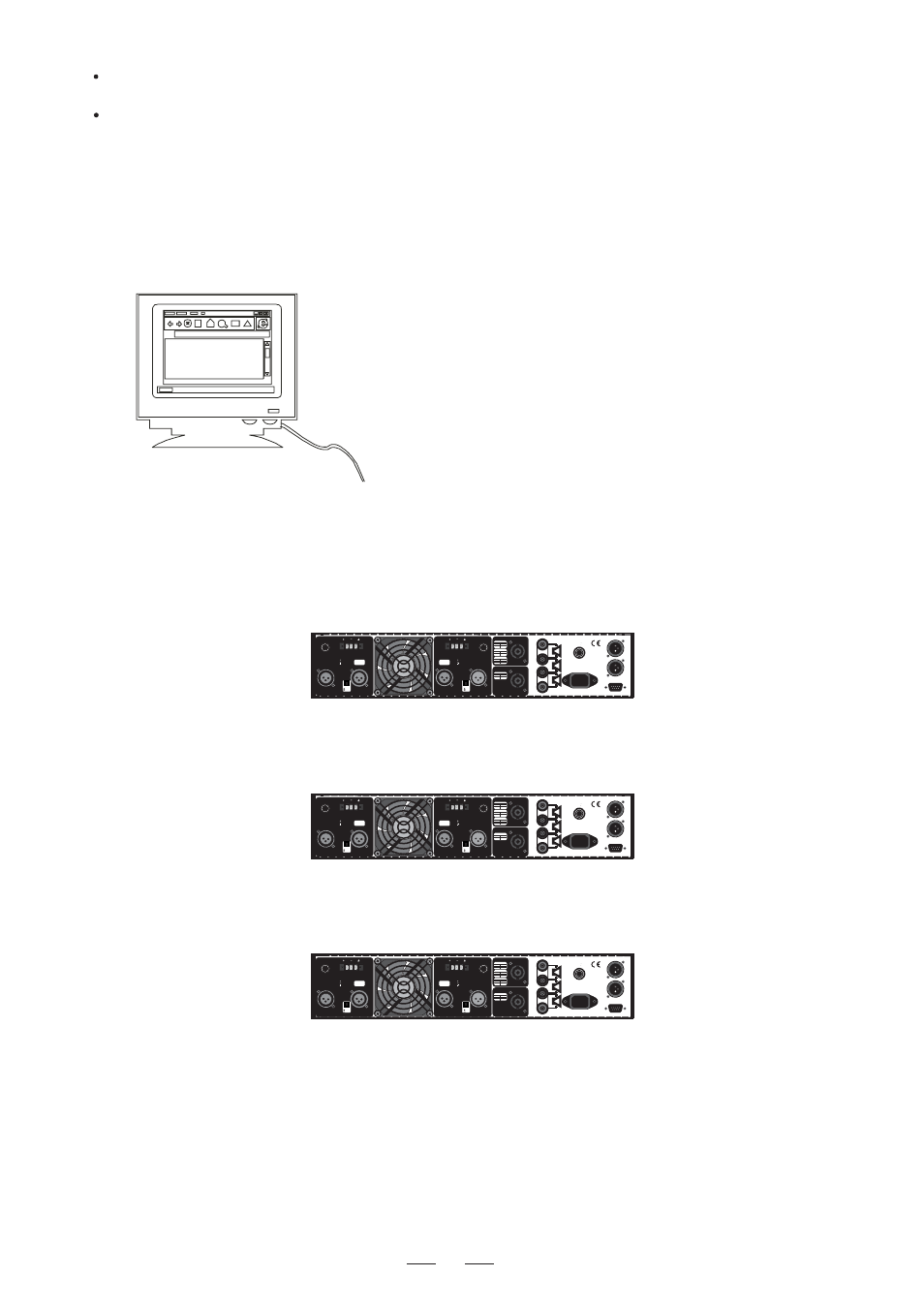
5.2 Connection to the PC
Connect the First DPA to the PC's RS232 serial port, using a 9-pin female plug connected to the RS232 socket
on
the rear panel of unit.
Connect RS485 IN of the Second DPA to the First DPA 's RS485 OUT socket, in this way, you can connect up
32 DPA units for a same PC.
to
IMPORTANT!!!
If the first unit is placed at a distance to the PC that exceeds 5 meters, RS232 to RS485 converters mu
st
be used to reach it. And the first unit connected to the PC thru RS232 must be switched ON and working,
otherwise none of the other units can be controlled by the PC.
Connection Diagram of Remote Control
5.3 First Steps with the PC Editor
To avoid accidentally overwriting an existing PRESET, it is important that you follow the correct routine when ini-
tiating a session between the DPA unit and your computer.
1>. With the
powered up and connected to your PC's serial port as described, run the PC Editor
DPA unit
program
by selecting the MAXI EOITOR icon in the Windows PROGRAMS menu.
8
R