Figure 2-46 power supply thermal connector – Asus P4B User Manual
Page 55
ASUS P4B motherboard user guide
2-33
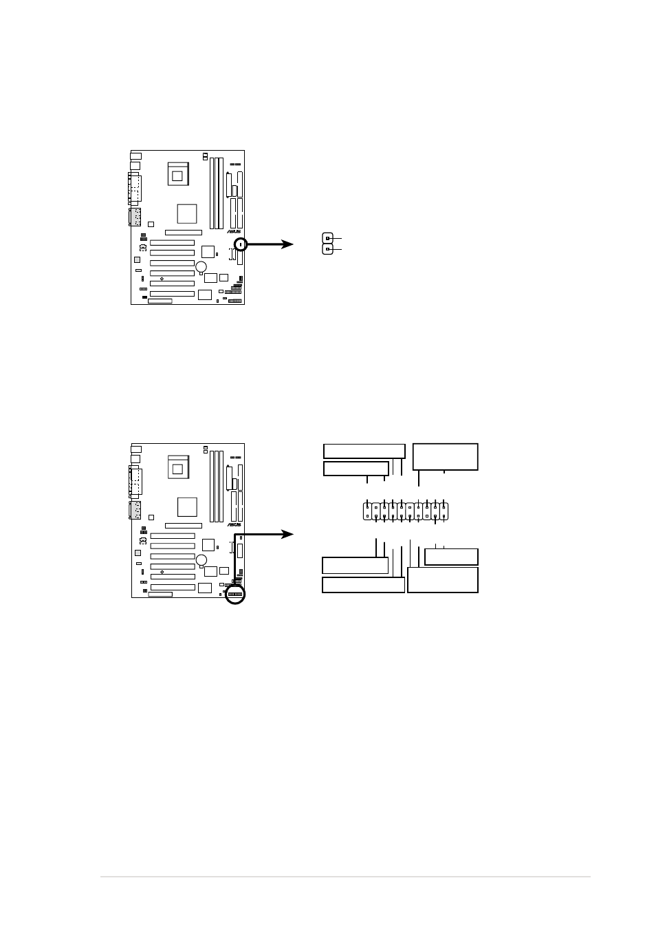
17. System panel connector (20-pin PANEL)
This connector accommodates several system front panel functions.
Figure 2-47
System Panel Connector
•
System Power LED Lead (3-1 pin PWR.LED)
This 3-1 pin connector connects to the system power LED. The LED
lights up when you turn on the system power, and blinks when the
system is in sleep mode.
•
Keyboard Lock Lead (2-pin KEYLOCK)
This 2-pin connector connects to a chassis-mounted switch to allow
the use of the keyboard lock feature.
P4B
®
P4B System Panel Connectors
*
Requires an ATX power supply.
PLED
Ground
MLED
PWR
+5 V
Keylock
+5V
Speaker
Speaker
Connector
Power LED
Ground
+5 V
Reset SW
SMI Lead
Message LED
ExtSMI#
Ground
Reset
Ground
Ground
Ground
Keyboard Lock
ATX Power
Switch*
16. Power supply thermal connector (2-pin TRPWR)
If your power supply has a thermal monitoring feature, connect its
thermal sensor cable to this connector.
P4B
®
P4B Power Supply Thermal Connector
TRPWR
Ground
TRPWR
Figure 2-46
Power Supply Thermal Connector
- Xonar DX (80 pages)
- Xonar DX (10 pages)
- PCI Express Audio Card Xonar DX (70 pages)
- Audio Card Xonar D2X (70 pages)
- Xonar D2X (88 pages)
- Xonar D2X (84 pages)
- D2X (88 pages)
- ROG Xonar Phoebus (72 pages)
- ROG Xonar Phoebus (122 pages)
- Xonar DSX (26 pages)
- Xonar DSX (29 pages)
- Xonar DGX (38 pages)
- Xonar DGX (33 pages)
- Xonar DGX (58 pages)
- Xonar DG (54 pages)
- Xonar DG (58 pages)
- Xonar DG (32 pages)
- Xonar DG (28 pages)
- Xonar Essence ST (35 pages)
- Xonar Essence ST (40 pages)
- Xonar Essence ST (53 pages)
- Xonar Essence ST (52 pages)
- Xonar DS (54 pages)
- Xonar DS (33 pages)
- Xonar Xense (70 pages)
- Xonar Xense (45 pages)
- Xonar Xense (47 pages)
- Xonar U3 (56 pages)
- Xonar U3 (38 pages)
- Xonar Essence STX (49 pages)
- Xonar Essence STX (10 pages)
- Xonar Essence STX (32 pages)
- XONAR D1 E4009 (72 pages)
- Xonar D1 (72 pages)
- Xonar D1 (80 pages)
- Xonar D1 (10 pages)
- Xonar Essence One (7 pages)
- Xonar Essence One (5 pages)
- Xonar HDAV 1.3 (100 pages)
- Motherboard M4A78-EM (64 pages)
- A7N8X-VM/400 (64 pages)
- K8V-XE (86 pages)
- K8V-XE (20 pages)
- M2R32-MVP (60 pages)
- M2R32-MVP (160 pages)