Lenovo B50-30 All-in-One User Manual
Page 53
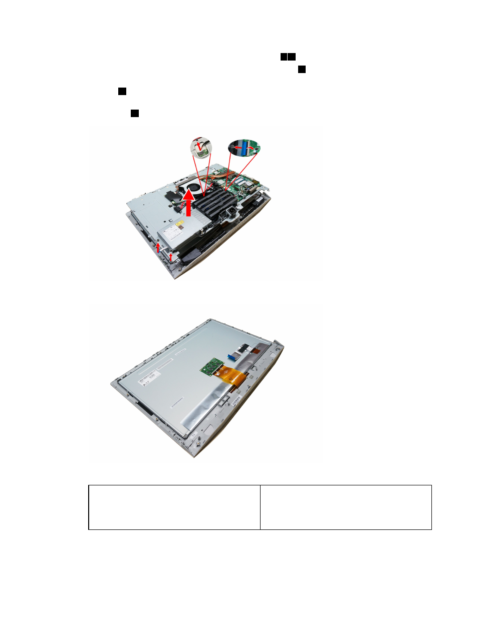
Step 15. Disconnect the LVDS cable from connector as shown.
1 2
Step 16. Disconnect the touch control board cables from connector.
3
Step 17. Disconnect the power switch board cables from connector. Refer to “Replacing the power switch
board”.
4
Step 18. Lift up the chassis from the bottom and disconnect the converter cable from the connector on the
LED panel.
5
Step 19. Lift up the chassis to separate the chassis from the LED panel module.
Step 20. To install the new the LED panel module:
The new LED panel module including:
1. LED panel
2. LVDS cable
3. Touch control board and touch cable. (Touch
model only)
a.
Line up the chassis with new LED panel module, place the chassis into position.
b.
Connect the converter cable to the connector on the LED panel.
47
This manual is related to the following products: