Pin xlr dmx connectors, Pin xlr to 5-pin xlr conversion – American Audio X-CALIBUR User Manual
Page 4
©
American DJ Supply
®
- www
.americandj.com - X-Calibur™ Instruction Manual Page 7
©
American DJ Supply
®
- www
.americandj.com - X-Calibur™ Instruction Manual Page 8
P
S
CS
DJ
S
Ma
e sure t
e
lamp is located in t
e
center o
t
e
re
lector t
en adjust t
e
lamp to t
e
best spot
nplug main power and wait
or at least
minutes be
ore
opening t
e
ousing
or installing
operating and maintaining t
e
de
ice
you
a
e
to be
uali
ied and
ollow t
e
instruction manual.
eplace
use
bulb or spare parts only wit
t
e
same type o
parts.
Ma
e sure t
at neit
er t
e
an nor t
e
enting slots are
co
ered by decorati
e material.
o user ser
icable parts inside.
CC
C
CP
C
C
D
D P
S S
CS
8
8
DMX
PC
M
M
P
DMX
P
DMX
S
DD SS
P
S
7 8
P
P
17
6
5
4
3
2
1.
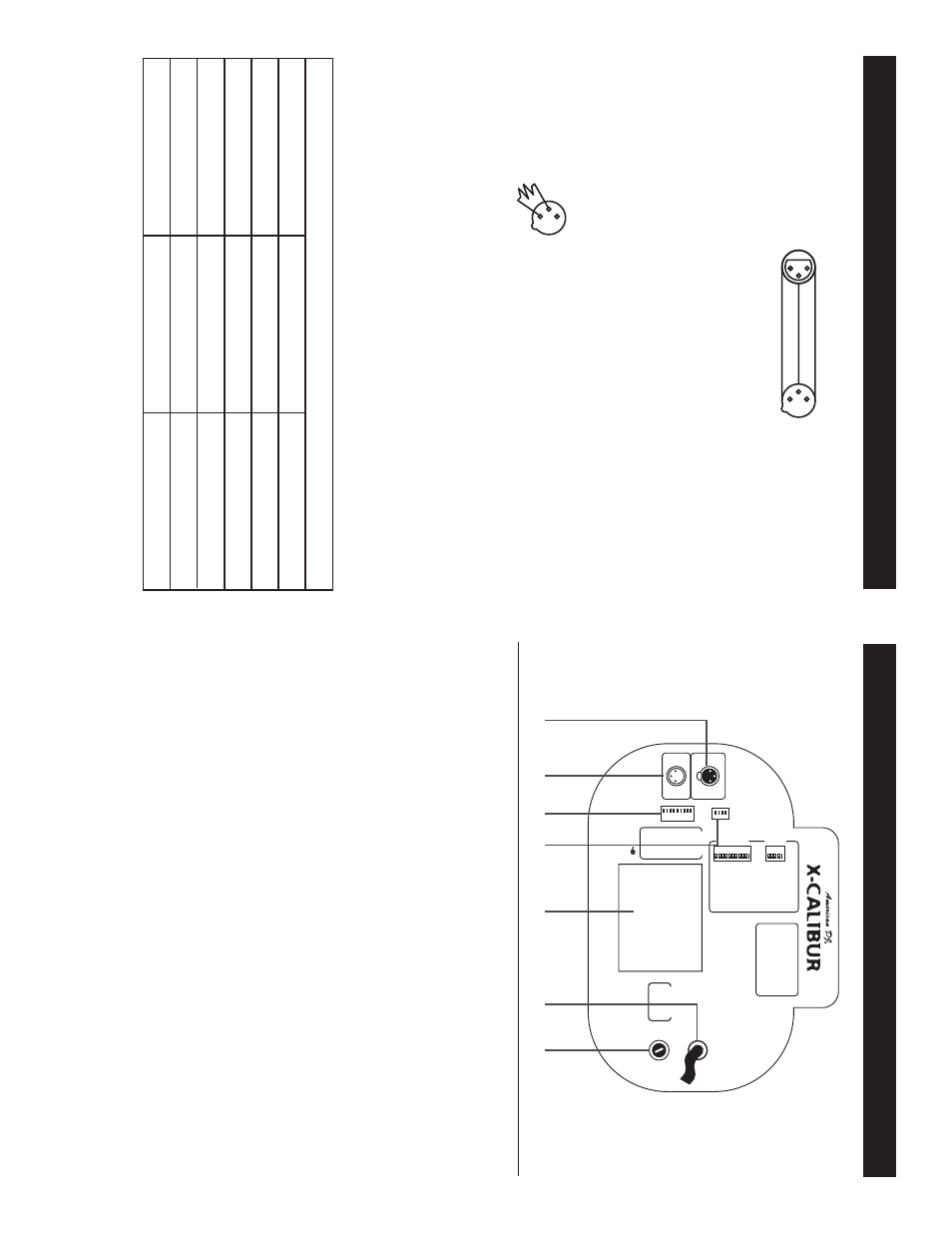
XLR Output Jack -
This jack is used to send the incoming DMX
signal to another fi
xture.
2.
XLR Input Jack -
This jack is used to accept a DMX input
signal.
3.
Dip Switches -
These switches are used to set the DMX
address. Each switch corresponds to a specifi
c value based
on binary code.
4.
Option switches -
These switches will activate one of four
options:
Switch 1:
Focus - When activated this switch will center
the mirror with a white spot.
This will allow you to focus the
beam properly.
Switch 2:
Self
T
est - When activate this function will acti-
vate a built in self test program.
Switch 3:
Inverted Pan - When activated this switch will
invert the P
AN value. Left will become right and vice
versa.
Switch 4:
Inverted
T
ilt - When activated this switch will
invert the
TIL
T
value. Up will become down and vice
versa.
5.
La
m
p
H
o
using -
This c
o
v
e
r enc
lose the lamp and lamp
so
c
k
e
t.
DMX512 IN
3-PIN XLR
1
2
3
1
2
3
DMX +
DMX -
COMMON
DMX512 OUT
3-PIN XLR
Figure 3
Special Note: Line T
ermination.
When longer runs of cable are
used, you may need to use a terminator on the last unit to avoid erratic
behavior
.
A
terminator is a 90-120 ohm 1/4 watt resistor which is con-
nected between pins 2 and 3 of a male XLR connector (DA
T
A
+ and
DA
T
A
-).
This unit is inserted in the female XLR connector of the last
unit in your daisy chain to terminate the line. Using a cable terminator
(ADJ part number ZDMX/T) will decrease the possibilities of erratic
behavior
.
1
2
3
Te
rmination reduces signal errors and
avoids signal transmission problems
and interference. It is always advisable
to connect a DMX terminal, (Resistance
120 Ohm 1/4 W) between PIN 2 (DMX-)
and PIN 3 (DMX +) of the last fixture.
Figure 4
5-Pin XLR DMX Connectors.
Some manufactures use 5-pin XLR
connectors for DA
T
A
transmission in place of 3-pin. 5-pin XLR fi
xtures
may be implemented in a 3-pin XLR DMX line. When inserting standard
5-pin XLR connectors in to a 3-pin line a cable adaptor must be used,
these adaptors are readily available at most electric stores.
The chart
below details a proper cable conversion.
Conductor
5-Pin XLR Male (In)
3-Pin XLR Female (Out)
Pin 1
Do Not Use
Do Not Use
Pin 3
Pin 2
Pin 1
Pin 3
Pin 2
Not Used
Not Used
Data T
rue
(+
signal)
Data Compliment (- signal)
Ground/Shield
3-Pin XLR to 5-Pin XLR Conversion
X-Calibur™
Set
Up
X-Calibur™
Fuse & Lamp Replacement