Kt-mod-inp16, Terminal connections – Kantech KT-MOD-INP16 User Manual
Page 2
Tel.: 1 (450) 444 2030
• Toll Free: 1-888-222-1560 • Fax: 1 (450) 444 2029 • Internet: www.kantech.com
DN1776-0809
Copyright © 2008 Tyco International Ltd. and its Respective Companies. All Rights Reserved.
• Specifications may change without notice.
Kantech and the Kantech logo are trademarks of Tyco International Ltd. and its Respective Companies.
KT-MOD-INP16
KT-400 Expansion Module 16-Zone Input with SPI Cable Install Sheet
4. Configurations
with
Jumpers
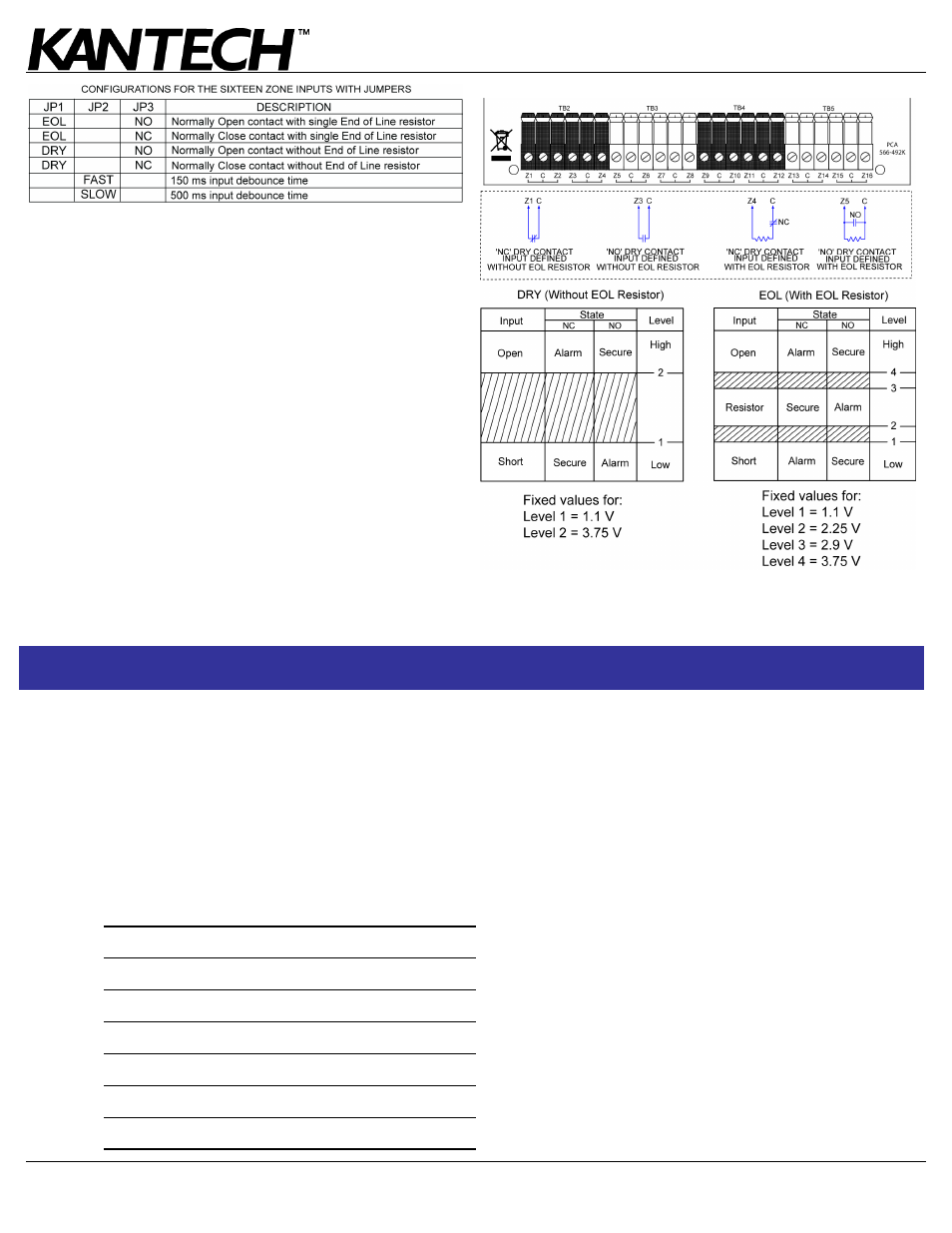
There are 3 jumpers available to configure the KT-MOD-INP16.
The jumper settings apply to ALL 16 inputs at the same time.
Note: Jumper JP4 is for future use.
DRY (without end-of-line resistor): In a simple NC dry contact
configuration, the secure state is given when a short is detected.
The voltage becomes lower than the Level 1 threshold value
(1.1V).
The alarm state is given when the input is open. The voltage
becomes higher than the Level 2 threshold value (3.75V). If the
alarm switch is programmed as NO device, the alarm state will
be given when the input is shorted.
EOL (with end-of-line resistor): For NC device, the secure
state is given when a single resistor is detected. The voltage
becomes lower than the Level 3 threshold value (2.9V) and
higher than the Level 2 threshold value (2.25V).
The alarm state is given when the input is open or short. The
voltage becomes higher than the Level 4 threshold value (3.75V)
or lowers than the Level 1 threshold value (1.1V). If the alarm
switch is programmed as NO device, the alarm state will be given
when a single resistor is detected.
5.
Applying Power
After all wiring is completed, connect the 16 VAC to the KT-400.
Connect the battery leads to the battery, and then apply power to
the AC transformer.
Note: Do not connect power until all wiring is complete.
Terminal Connections
Module no.: ______________________________________________________________________________________
Date of installation: _______________________________________________________________________________
KT-400 Name: ____________________________________________________________________________________
KT-400 SITE NAME: _______________________________________________________________________________
KT-400 Serial Number: _____________________________________________________________________________
AUX: ___________________________________________________________________________________________
SPI BUS (FROM): _________________________________________________________________________________
SPI BUS (TO): ____________________________________________________________________________________
F
Z1:
F Z9: __________________________________________
F
Z2:
F Z10: _________________________________________
F
Z3:
F Z11: _________________________________________
F
Z4:
F Z12: _________________________________________
F
Z5:
F Z13: _________________________________________
F
Z6:
F Z14: _________________________________________
F
Z7:
F Z15: _________________________________________
F
Z8:
F Z16: _________________________________________