Dimensions, Aa-2, Plus the threaded rod end dimension – Sheffer AA SERIES User Manual
Page 3: 16 holes on sides of head
31
/
32
9
/
16
9
/
16
1
/
4
NPT
1
/
2
DIA.
ROD
P + STROKE
ZJ + STROKE
SN +
STROKE
LB +
STROKE
1
1
15
/
32
3
/
4
7
/
16-
20
7
/
16
WRENCH
FLATS
3
/
8
-16
1
/
2
" DEEP ON 1
1
/
2
" BORE,
5
/
8
" DEEP ON
2, 2
1
/
2
" BORES (3) HOLES EACH HEAD
1
/
4
-28
5
/
16
" DEEP ON HEAD,
1
/
2
"
DEEP ON CAP (4) HOLES EACH HEAD
E/2
TN
TN
E
E
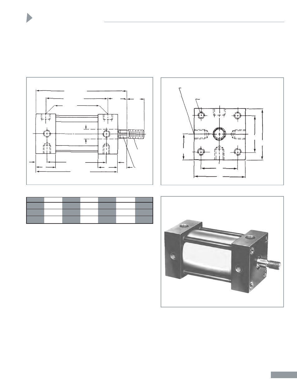
Dimensions for Cusioned Cylinders
Adding a cushion or cushions to a cylinder increases overall
length. A front cushion or rear cushion adds 1 inch to all plus
stroke dimensions. Cushioning a cylinder on both ends adds 2
inches to all plus stroke dimensions.
Double Rod End Cylinders
All dimensions shown below remain unchanged. Second rod
(not shown in dimension drawing) will extend from face of
head the total of the stroke plus
15
/
32
" plus the threaded rod
end dimension.
BORE
E
LB*
P*
SN*
TN
ZJ*
1
1
/
2
2
2
7
/
8
1
7
/
8
1
3
/
4
1
7
/
16
3
11
/
32
2
2
1
/
2
2
7
/
8
1
7
/
8
1
3
/
4
1
27
/
32
3
11
/
32
2
1
/
2
3
3
2
1
7
/
8
2
3
/
16
3
15
/
32
*Plus Stroke Dimensions
Universal Mount
The basic cylinder is equipped with Universal Mounting Holes
that permit side flush mount, front head mount and rear head
mount. Using optional mounting kits, shown on Page AA-3,
complete versatility is achieved to satisfy any mounting
requirement and to do so economically.
TP-AA Trunnion Pin Assemblies thread into
3
/
8
–16 holes on
sides of head.
NOTE:
For Pivot and Clevis Bracket Mounts, use Mounting
Brackets dimensioned on Page AA-3. Use
1/4
–28 Cap Screws
supplied to bolt brackets to rear head.
Front Flange, Rear Flange and Foot Bracket Mount use
Universal Mounting Brackets (See Page AA-3).
Affix brackets by using
3
/
8
–16 holes on sides of head and
FMS-AA mounting screws.
Use
1
/
4
–28 cap screws supplied to bolt brackets to each head
as shown.
Dimensions
AA-2