MSI GF615M-P31 User Manual
Page 18
8
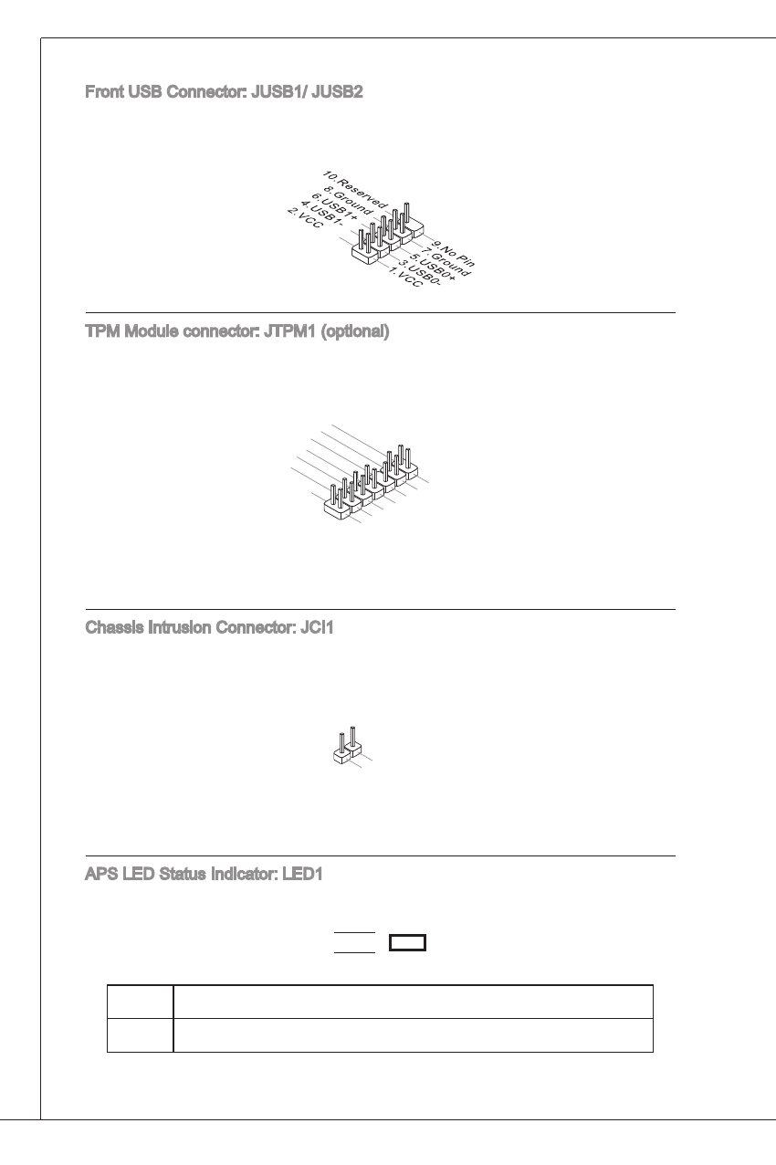
Front uSB Connector: JuSB/ JuSB2
this connector, compliant with intel
®
i/o Connectivity design Guide, is ideal for
connecting high-speed uSB interface peripherals such as uSB Hdd, digital cam-
eras, MP3 players, printers, modems and the like.
tPM Module connector: JtPM (optional)
this connector connects to a tPM (trusted Platform Module) module. Please re-
fer to the tPM security platform manual for more details and usages.
10.N
o Pin
14.G
roun
d
8.5V
Pow
er
12.G
roun
d
6.Se
rial IR
Q
4.3.3
V Po
wer
2.3V
Stan
dby p
ower
1.LP
C Clo
ck
3.LP
C Re
set
5.LP
C ad
dres
s & d
ata p
in0
7.LP
C ad
dres
s & d
ata p
in1
9.LP
C ad
dres
s & d
ata p
in2
11.L
PC a
ddre
ss &
data
pin3
13.L
PC F
ram
e
Chassis intrusion Connector: JCi
this connector connects to the chassis intrusion switch cable. if the chassis is
opened, the chassis intrusion mechanism will be activated. the system will record
this status and show a warning message on the screen. to clear the warning, you
must enter the BioS utility and clear the record.
1.CIN
TRU
2.Gro
und
aPS Led Status indicator: Led
these aPS (active Phase Switching) Led indicates the current CPu power phase
mode. Follow the instructions below to read.
Led
on
the Led will light when CPu is in 3 phase power mode.
oFF
the Led off when CPu is in phase power mode.