Front panel i/o connectivity design guide – MSI H61M-P21 (B3) User Manual
Page 18
8
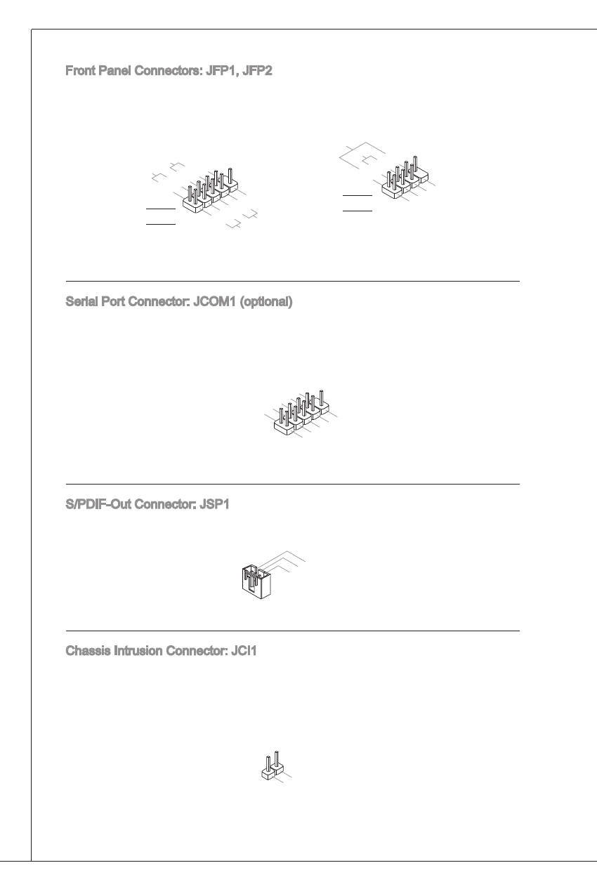
Front Panel Connectors: JFP, JFP2
these connectors are for electrical connection to the front panel switches and
Leds. the JFP is compliant with intel
®
Front Panel i/o Connectivity design
Guide.
1.+
3.-
10.N
o Pin
5.-
Rese
t Sw
itch
HDD
LED
Pow
er Sw
itch
Pow
er LE
D
7.+
9.Re
serve
d
8.-
6.+
4.-
2.+
JFP
1.Gro
und
3.Su
spen
d LE
D
5.Po
wer L
ED
7.No
Pin
8.+
6.-
4.+
2.-
Buzz
er
Spea
ker
JFP2
Serial Port Connector: JCoM (optional)
this connector is a 6550a high speed communication port that sends/receives
6 bytes FiFos. you can attach a serial device.
1.DC
D
3.SO
UT
10.N
o Pin
5.Gro
und
7.RT
S
9.RI
8.CT
S
6.DS
R
4.DT
R
2.SIN
S/PdiF-out Connector: JSP
this connector is used to connect S/PdiF (Sony & Philips digital interconnect
Format) interface for digital audio transmission.
3.VC
C
2.SP
DIF
1.Gro
und
Chassis intrusion Connector: JCi
this connector connects to the chassis intrusion switch cable. if the chassis is
opened, the chassis intrusion mechanism will be activated. the system will record
this status and show a warning message on the screen. to clear the warning, you
must enter the BioS utility and clear the record.
1.CIN
TRU
2.Gro
und