8 valve air bag plumbing & wiring diagram, Air tank – HornBlasters AC-AZ User Manual
Page 2
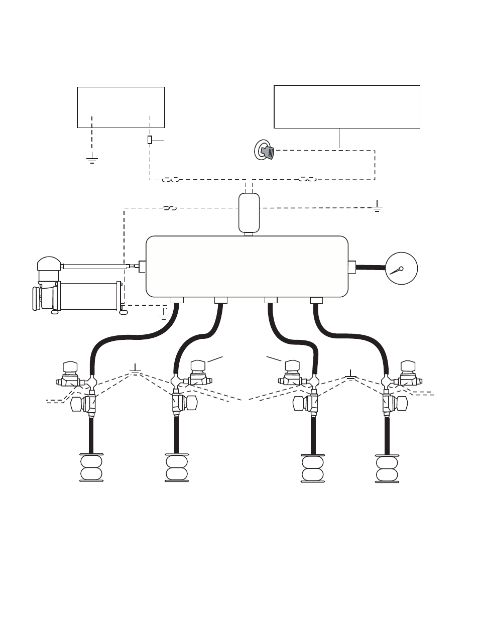
Compressor Load
(White)
+
-
30A Fuse
Fused Positive
Power Source (Red)
12G A
WG
12G A
WG (R
ed)
Trigger/Switch Positive
(Small Red or Blue)
Air Compressor
12V Battery
Hornblasters, Inc.
39440 Pattie Road
Zephyrhills, FL 33540-3158
Phone: +1 (877) 209-8179
Fax: +1 (813) 783-2407
email: [email protected]
8 Valve Air Bag Plumbing & Wiring Diagram
Ignition Wire
Run this wire to an ignition wire (this is a wire that
is only powered when the key is turned to the on
position). This will insure that the air compressor
will not run when the car is turned off and drain
your batteries.
Ground (Black)
0
20
40
60 80 100
120
140
160
Air Gauge
Tank Pressure
To
Switchbox
To
Switchbox
Dump Valve
Dump Valve
Dump Valve
To Switchbox
HORNBLASTERS.COM
AIR TANK
Pr
essur
e
Swit
ch
Ground (Black)