Important – FMI SCST-01 User Manual
Page 6
http://www.fmipump.com
"SCST-01" STEP MOTOR
CONTROL KIT
OPERATION INSTRUCTIONS
IN-SCST-01-10 6
PHASE
⎯A
6
PHASE A
5
PHASE
⎯B
4
PHASE B
3
+ SUPPLY LEAD
2
− SUPPLY LEAD
1
TRIM POT
SENSOR POWER
9
SENSOR SIGNAL
8
SENSOR GROUND 7
SENSOR ANODE
6
SENSOR CATHODE 5
START SIGNAL
4
START COMMON
3
0-5 VDC INPUT
2
0-5 VDC COMMON
1
Dispense Pins
Speed or rpm Pins
SPEED HEADER - J3
4.0 Features
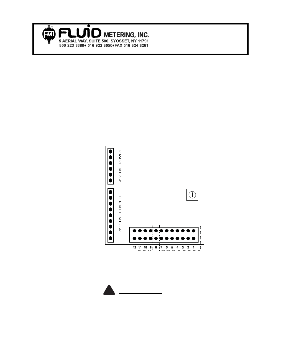
4.1 Trim
Pot
Factory set at (approx.) For motors P/N 110746, 300615 the trim pot is factory set at
1.75 amp/phase. The trimming potentiometer (see Figure 2 for approximate location) is
used to limit the amount of current used by the controller in driving the stepper motor.
Turning the potentiometer clockwise will provide more current to the motor, while turning
it counter-clockwise will reduce the current supplied.
Figure 2
IMPORTANT
Additional heat sinking may be required when operating above 2.5 amps per phase.
Contact factory for additional information.
!