Duff-Norton SK6415-300 (SPA Series DC) User Manual
Page 14
6-2.
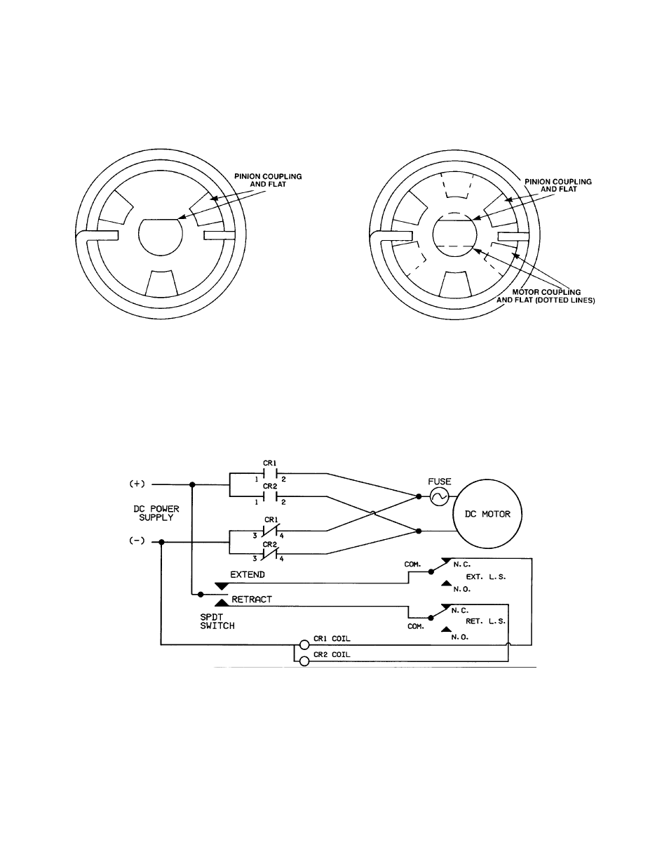
LIMIT SWITCH WIRING DIAGRAM
6-1.
Brake Alignment
SECTION VI
TECHNICAL ILLUSTRATIONS
14
FIGURE 6-2. LIMIT SWITCH WIRING DIAGRAM,
6415 SERIES DC ACTUATOR
Figure 6-1A. Brake, Spring,
Motor and Pinion Coupling
Alignment
Figure 6-1B. Brake Spring,
Motor and Pinion Coupling
Alignment
NOTE
Duff-Norton’s PDC Series Control Box or Two SPDT
relays must be used to avoid burning up the limit switches.