Duff-Norton Machine Screw Translating 2 Ton - 75 Ton User Manual
Page 6
6
as required.
7. Install top load bearing (7) or bearing cup on
worm gear (6A) or worm gear and nut assembly
(6B).
8. Fill housing fully with grease.
9. Install shell cap (2) and screw down until tight.
Note
Shell cap flange does not necessarily have to
bear against top of shell, there will usually be a
gap. This will put a slight drag on the worm. If
worm is hard to turn, back off slightly on the
shell cap.
10. Lock base plate in place with set screws.
Note
If new parts have been installed, it may be
necessary to respot holes for these screws.
11. Screw bottom pipe (4) into shell (3) (upright
models) or into shell cap (2) (inverted models).
12. Brush lifting screw (5) with a light film of grease
and install in actuator. On inverted models,
install guide bushing (16) and then install lifting
screw (5).
13. If actuator is keyed, install key in shell cap (2)
and bolt in place.
14. Operate unit to ensure proper functioning of all
components prior to reinstallation.
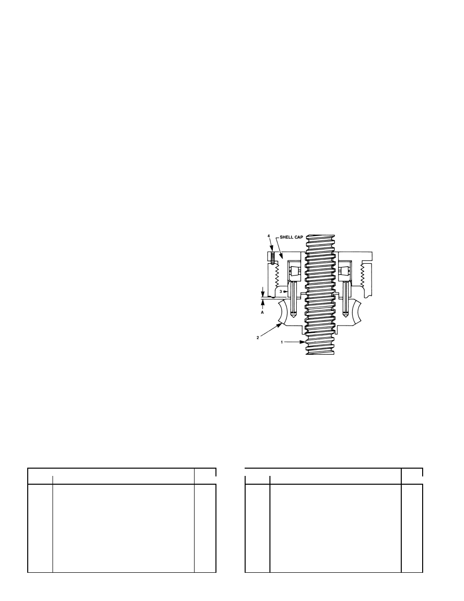
2-8. Anti-Backlash Nut Function
As shown in Figure 2-1, the worm gear (2) and
anti-backlash nut (3) are pinned together with guide
pins. The threads in the anti-backlash nut work in
opposition to the threads in the worm gear as they
engage the threads of the lifting screw (1). Adjust-
ment of backlash is made by running down on the
shell cap of the actuator. This forces the anti-back-
lash nut threads into closer contact, reducing clear-
ance and thus reducing backlash.
2-9. Anti-Backlash Nut Adjustment
1. To minimize backlash remove the two set
screws (4) and tighten down on shell cap until
the desired backlash is obtained. Spot drill top of
shell through set screw holes, then replace set
screws and tighten to prevent shell cap backing
off.
2. To avoid binding and excessive wear, do not
adjust lifting screw backlash to less than 0.002
inch.
3. The clearance (A) designed into the worm gear
and anti-backlash nut set is one-half the thread
thickness. When adjustments have been made
to use all this clearance replace the worm gear
and anti-backlash nut as a set.
Figure 2-1.
Anti-Backlash Nut Adjustment
Section III
Illustrated Parts List
3-1. General
This section contains an exploded illustration of the
1800, 9000, 4800 and 9400 Series translating machine
screw actuators. The number adjacent to each part on
the illustration is the index number. Keyed to this index
number on the parts list is the part name.
When ordering parts be sure to include:
1. The nameplate model of your unit.
2. Index number and name of part.
3-2. Parts List For 1800 (2000), 9000 (10000), 4800 (5800) and 9400 (10400) Series Translating
Machine Screw Actuators.
I n d e x
Q t y .
I n d e x
Q t y .
N o .
Part Name
R e q .
N o .
Part Name
R e q .
1
Screw, Set
1
9
Screw, Cap
1 2
2
Cap, Shell
1
1 0
Washer, Lock
1 2
3
Shell, Actuator
1
1 1
Flange, Worm
2
4
Pipe, Bottom
1
1 2
Shim, Flange
2
5
Screw Assembly, Lifting
1
1 3
Seal, Oil
2
6 A
Worm Gear
1
1 4
Worm
1
6 B
Worm Gear and Anti-backlash Nut
Assembly (Mfg’d and sold in sets
only)
1
1 5
Bearing, Worm
2
7
Bearing, Top Load
1
1 6
Bushing, Guide (inverted model o
1
8
Bearing, Bottom Load
1
1 8
Nameplate
1