CPI Communications LE Series User Manual
Page 3
2.0 General Description
The LE series local extensions are designed to provide remote control of an in-house conventional or trunked
two way radio base station or repeater from a distance of up to 1000 feet.
The LE series is available in four different housing configurations. They are: the LE10 telephone style unit with
handset, the LE20 desktop console with desk microphone, the LE30 desktop console with built in electret
condenser microphone and the LE40 desktop console with goose neck microphone.
Standard features on all LE models include front panel PTT switch, LED transmit indicator, one watt amplified
speaker with volume control and adjustable amplified modulation output.
In addition to the above listed features, the console models LE20, 30 and 40, offer as standard features a panel
mounted CTCSS (monitor) disable and intercom capability between units.
The LE10, 20, 30 and 40 may be wall mounted by ordering the -WM option. When wall mounting the LE20
please note, no provisions are made for mounting the desk microphone.
LE series units may be powered by the radio power supply or by ordering the optional wall plug-in transformer,
-WP option.
3.0 Installation Considerations
The LE series local extension will work with any radio system that will accept a 2 mVRMS to 565 mVRMS
microphone audio input level and provides an 88 mVRMS to 880 mVRMS receive audio output level.
If the radio is going to be used as a control point, the receive audio should be taken from a point after the squelch
circuit that is unaffected by the radio's volume control.
If the radio is not going to be used as a control point, speaker output may be used by setting the radio's volume
control for a level that falls into the above range.
The LE series requires 12 to 16 VDC @ 175 mA. This may be supplied from a central source at the radio site
using a conductor in the hook-up cable or by using the -WP option.
18 to 22 gauge multi-conductor cabling is recommended with the number of conductors determined by the
application and options installed.
A minimum configuration will use 4 conductors, a maximum will use 14.
3.1 Connections
Remove the top half of the housing by removing the four housing screws. The multi-conductor hook-up cable
should be threaded through the opening provided in the lower left corner on the rear of the unit. Proceed by making
the necessary connections to terminal blocks TB1 and TB2 (when included). The terminal blocks are detachable
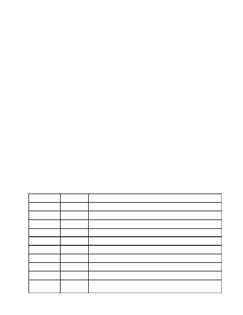
from the circuit board to allow easier access to the screw terminals. Table 1 describes the pin-out of TB1. Table
2 describe the pin-out of TB2.
Table 1
2
Terminal #
Description
Function
1
RX HI
Receive audio from radio.
2
RX LO
Recieve audio return for non-ground referenced receive audio sources.
3
PTT HI
Available option. Connect to +V for radios that key to plus voltage.
4
PTT
PTT line from radio.
5
GND
Ground from radio.
6
MOD OUT
Microphone input to radio.
7
MON C
Common contact of the form "C" monitor relay.
8
MON NC
Normally closed contact of the form "C" monitor relay.
9
MON NO
Normally open contact of the form "C" monitor relay.
10
+12 VDC
Power supply voltage from radio. Not used if LE unit was ordered with
-WP option.