DuraVent PolyPro User Manual
Page 4
4
LISTING
Listed to ULC S636
Rated Class IIA, IIB, and IIC vent system
maximum temperature 230°F (110 °C)
maximum positive pressure 15 in-w.c.
Massachusetts Plumbers Board,
# G1-0811-42
APPLICATION
ANSI Category II and IV gas-burning
appliances
Appliances specifically tested and listed to
use M&G DuraVent PolyPro Venting
PERMITS
Check with your local Building Official, Fire
Official, or other authority having jurisdiction
regarding permits, restrictions, and
installation inspections in your area.
GENERAL INSTALLATION NOTES
Read these instructions before beginning.
You must use only authorized M&G DuraVent
PolyPro vent parts, or other parts specifically
authorized in these instructions and/or listed
by the appliance manufacturer in order to
maintain a safe, approved system.
•
Do not fill any air space clearance
(Table 1) with insulation.
•
Do not mix parts or try to match with
other products or use improvised
solutions.
•
Do not install damaged or modified
parts.
•
Use soapy water to lubricate gaskets.
•
Never use Petroleum base lubricants.
If these directions and those of the appliance
manufacturer differ, follow the more
conservative requirements. If you have any
questions, contact either your dealer or M&G
DuraVent directly. A venting system must
not be routed into, through, or within any
other vent, such as an existing masonry or
factory-built chimney flue, unless that vent
or chimney is not being used to vent another
appliance and is only used as a conduit for
the gas-vent system. Plastic venting systems
shall not pass through fire rated separations
without approved firestopping.
Refer to the appliance manufacturer's
instructions for maximum and minimum
vent lengths permitted with your specific
appliance model. This information should
include guidance on the maximum number
of elbows and related pressure-drops. The
total vent length from the appliance to
the termination shall not be greater than
specified by the appliance manufacturer.
If specific guidance is not offered by the
appliance manufacturer as to Equivalent
Vent Lengths (EVL) for vent components, the
general guidelines in Table 2 can be used.
CONDENSATE DRAIN (Fig.1)
Refer to the appliance manufacturer’s
installation instructions for requirements of
condensate drainage. Ensure proper system
slope for drainage. (Fig.7)
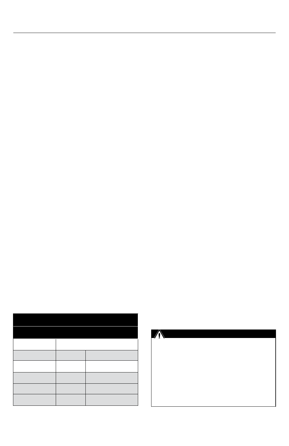
Table 1
Clearance to Combustibles
VENT PIPE ORIENTATION
Single Wall
Vertical
Horizontal
Up to 190°F
0"
0"
Up to 230°F
0"
¼" (6mm) all around
Concentric
Up to 230°F
0"
0"
The vent system must be compliant in
accordance with local code requirements
and appropriate National Codes: In
the US: NFPA 54 / ANSI Z223.1 National
Fuel Gas Code or the International Fuel
Gas Code. In Canada: CAN/CGA-B149.1
Natural Gas Installation Code or CAN/CGA-
149.2 Propane Installation Code.
IMPORTANT