Figure 2: the auto edid button on the 610t, Figure 3: connecting the fiber optic cables, Figure 2 – Kramer Electronics 610T User Manual
Page 8
6
610T, 610R - Using the Detachable Optical DVI System
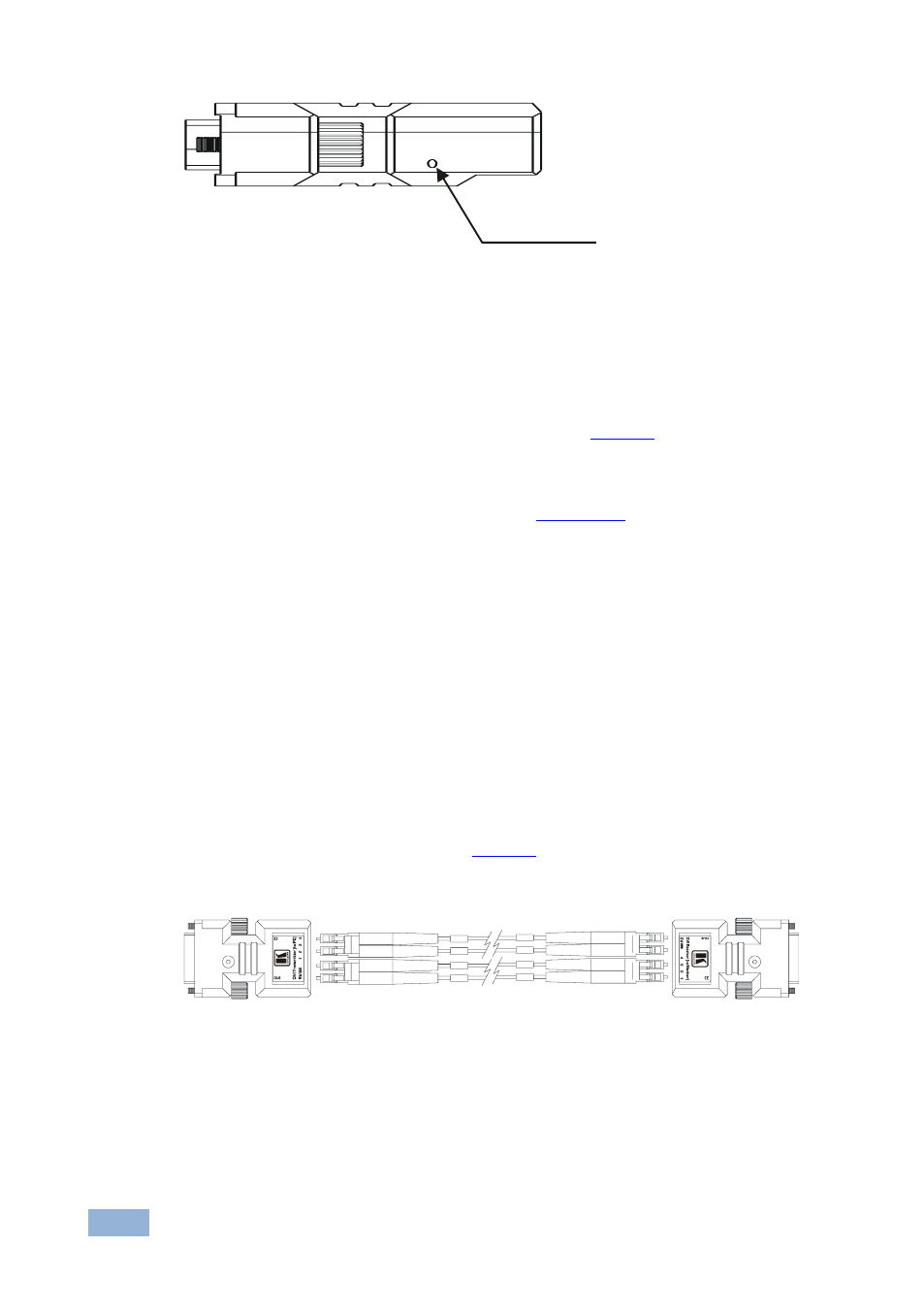
Figure 2: The Auto EDID Button on the 610T
4.2
Connecting the Detachable Optical DVI
Transmitter/Receiver
To connect the 610T Detachable Optical DVI Transmitter with the 610R
Detachable Optical DVI Receiver, as the example in
following:
1. Set the EDID of the display device (see
Section
2. Plug the 610T DVI connector directly to the DVI connector of the computer.
Do not use any intermediate cable or adapter between them.
3. Connect the 610R to the 5V DC power adapter and connect the adapter to
the mains electricity. The Indication LED is on.
4. Connect the 610R DVI connector directly to the DVI connector of the display
device.
Do not use any intermediate cable or adapter between them.
5. Connect the duplex LC fiber cables to the 610T and 610R modules, one
cable at a time, as illustrated in
Two duplex LC receptacles connected to two duplex LC patch cord multimode glass of
fibers with a 62.5/125
m or a 50/125
m core.
Figure 3: Connecting the Fiber Optic Cables
6. Turn ON the Power on the computer and the display device.
7. If the transmitter does not power up, connect the 5V power adapter to the
610T transmitter, and connect the adapter to the mains electricity.
T
h
e
A
u
t
o
E
D
I
D
B
u
t
t
o
n
1
2
3
4
1
2
3
4
610T Transmitter
610R Receiver