2 setting the addr dip-switches, 3 setting the baud dip-switches, 4 selecting hardware/software mode – Kramer Electronics VP-14xl User Manual
Page 9: Setting the addr dip-switches, Setting the baud dip-switches, Selecting hardware/software mode, Table 5: serial port baud rate dip-switch setting, On 6.2, On 6.4, N 6.2
Setting the DIP-switches on the VP-14xl
7
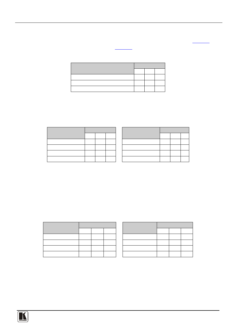
6.2 Setting the ADDR DIP-switches
DIP-switches 2, 3 and 4 set either the reply source (in Hardware mode
) or
machine number (in Software mode
).
Table 3: Hardware Mode Reply Source DIP-switch Setting
Reply Source
DIP-switch
2
3
4
Reply is taken from output 1 (default) ON OFF OFF
Reply is taken from output 2
OFF ON OFF
Reply is taken from output 3
OFF OFF ON
Note: When there is more than one VP-14xl attached to the RS-485 bus only one
unit can have a reply source set, all other units must have DIP-switches 2, 3 and 4
set to OFF.
Table 4: Software Mode RS-485 Machine Number DIP-switch Setting
Machine Number
DIP-switch
Machine Number
DIP-switch
2
3
4
2
3
4
1
OFF OFF OFF
5
OFF OFF ON
2
ON OFF OFF
6
ON OFF ON
3
OFF ON OFF
7
OFF ON ON
4
ON ON OFF
8
ON ON ON
When there is more than one VP-14xl attached to the RS-485 bus each unit must
have a unique machine number.
6.3 Setting the BAUD DIP-switches
DIP-switches 5, 6 and 7 set the serial port baud rate in both Hardware and
Software modes.
Table 5: Serial Port Baud Rate DIP-switch Setting
Baud Rate
DIP-switch
Baud Rate
DIP-switch
5
6
7
5
6
7
1200
OFF OFF OFF
19200
OFF OFF ON
2400
ON
OFF OFF
38400
ON OFF ON
4800
OFF ON
OFF
57600
OFF ON ON
9600 (default)
ON
ON
OFF
115200
ON ON ON
6.4 Selecting Hardware/Software Mode
DIP-switch 8 sets the operating mode to either Hardware or Software mode.
When the DIP-switch is:
•
OFF, the unit is set to Hardware mode (default)
•
ON, the unit is set to Software mode