Kramer Electronics VM-100CB User Manual
Page 9
Connecting the VM-100CB
7
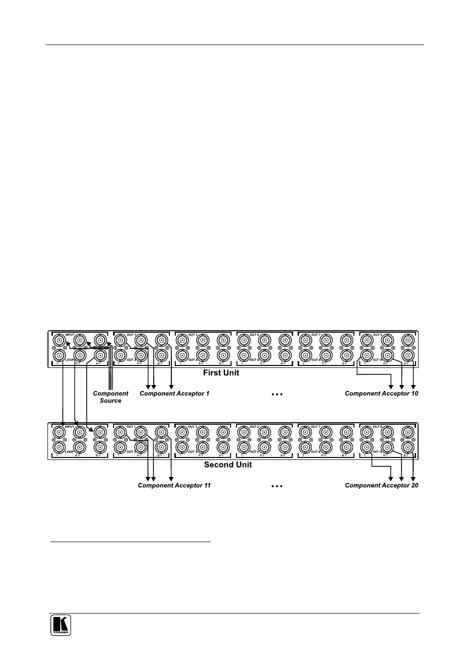
5.2 Connecting Several VM-100CB Units
You can connect several
VM-100CB units to form an expanded video
component distributor. For example, as Figure 4 illustrates, connect two
VM-100CB units to form a 1:20 Video Component Distributor.
To connect several
VM-100CB units, do the following
1
:
1. Connect a component video source (for example, a Betacam VCR) to the
BNC INPUT connectors on the first
VM-100CB unit.
2. Connect the LOOP BNC INPUT connectors on the first
VM-100CB unit
to the BNC INPUT connectors on the second
VM-100CB unit.
3. Set all three underside TERMINATION switches: B-Y, R-Y, and Y to
HI-Z (for looping: slide to the right) on the first
VM-100CB unit, and set
all three underside TERMINATION switches: B-Y, R-Y, and Y to 75
(for termination: slide to the left) on the second
VM-100CB unit.
4. Connect the component video output connectors
2
, as follows:
On the first
VM-100CB unit, to component video acceptors 1 to 10
On the second
VM-100CB unit, to component video acceptors 11 to 20
5. Connect both power cords
3
(not illustrated in Figure 4).
Figure 4: Connecting Several VM-100CB Units
1 Switch OFF the power on each device before connecting it to a VM-100CB unit. After connecting all VM-100CB units,
switch on their power and then switch on the power on each device
2 When less than the maximum outputs are required, connect only those outputs that are required, and leave the other outputs
unconnected
3 We recommend that you use only the power cords that are supplied with these machines