Kramer Electronics 123Vxl User Manual
Page 8
KRAMER: SIMPLE CREATIVE TECHNOLOGY
Connecting Differential Video Line Amplifier Units
6
6
Connecting Differential Video Line Amplifier Units
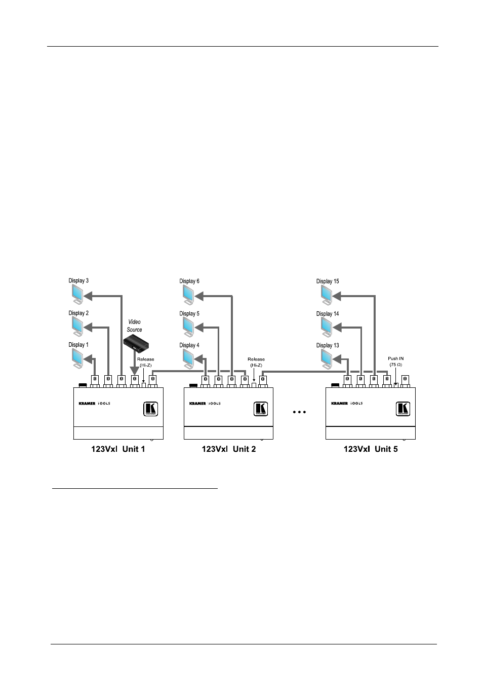
You can connect up to five
123Vxl Differential Video Line Amplifier units,
to provide up to 15 outputs, as Figure 3 illustrates.
To connect up to five
123Vxl Differential Video Line Amplifier units:
1. Connect the video source to the CV IN BNC connector on the first unit.
2. Connect the LOOP BNC connector on each unit to the CV IN BNC
connector on the next unit in the line, respectively
1
.
3. Connect the OUT 1, OUT 2 and OUT 3 BNC connectors on each unit to the
appropriate video acceptors
2
, as required.
4. Release the TERM switch (selecting Hi-Z) on all units, except on the last
(fifth) unit. Push in the TERM switch on the last (fifth) unit (selecting
75 ).
5. If required, adjust
3
the output signal level and/or cable compensation
equalization level on each unit.
Figure 3: Connecting 123Vxl Differential Video Line Amplifier Units
1 Connect the LOOP BNC connector on the first unit to the CV IN BNC connector on the second unit. Connect the LOOP
BNC connector on the second unit to the CV IN BNC connector on the third unit. Connect the LOOP BNC connector on the
third unit to the CV IN BNC connector on the fourth unit. Connect the LOOP BNC connector on the fourth unit to the CV IN
BNC connector on the fifth unit. Leave the LOOP BNC connector on the fifth (last) unit unconnected
2 Connect the OUT 1, OUT 2 and OUT 3 BNC connectors on the first unit to the video acceptors 1, 2 and 3, respectively.
Connect the OUT 1, OUT 2 and OUT 3 BNC connectors on the second unit to the video acceptors 4, 5 and 6, respectively.
Connect the OUT 1, OUT 2 and OUT 3 BNC connectors on the third unit to the video acceptors 7, 8 and 9, respectively.
Connect the OUT 1, OUT 2 and OUT 3 BNC connectors on the fourth unit to the video acceptors 10, 11 and 12, respectively.
Connect the OUT 1, OUT 2 and OUT 3 BNC connectors on the fifth unit to the video acceptors 13, 14 and 15, respectively
3 Use a screwdriver to carefully rotate the trimmer, adjusting the appropriate level