Kramer Electronics 103YC User Manual
Page 11
Kramer Electronics, Ltd.
9
9.3 C Phase Control (VM-9YC only)
When long cables are used in any video setup, phase shift occurs due to stray capacitance and inductance as
well as for other cable related reasons, resulting in signal distortion and thus depreciation in the quality of
picture. The colors may be wrong and the color information may be delayed more than the black and white
information, causing a "misprinted" image. The inputs and the outputs of the machine in use should match
perfectly to the cables used in order to avoid all sorts of unwanted phenomena, which deteriorate the final
image. The cables leading to and from the amplifier should be of the best quality and have the same length to
avoid cross delay problems. It is possible to compensate for the phase (delay) problem by using the C Phase
Control function of the VM-9YC. To correct the incoming video signal, adjust the
C Phase knob until a
satisfactory and true color picture is achieved.
9.4 C Gain Control (VM-9YC, 103YC only)
C Gain Control function enables the operator to control the C signal level to compensate for color loss resulting
from the use of long cables. Using a non-standard or an uncalibrated video source also affects the incoming
signal. To correct the incoming video signal, the
C Gain knob is adjusted to a satisfactory level until a proper
saturated picture is achieved.
9.5 HF (EQUALIZATION) Control
The HF Control function compensates for degradation of the video signal in high frequencies due to long or
non-standard cables. Popular cables such as the RG-59, RG-11 or the RG-179 signal cause
degradation/attenuation as shown in the following Table 5:
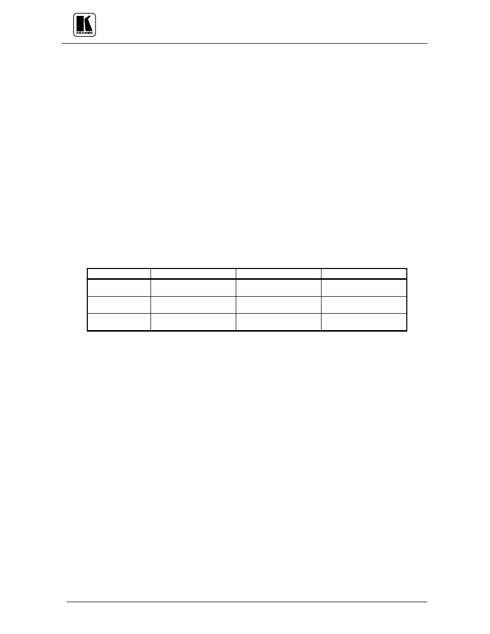
Table 5: Cable Degradation/Attenuation List
CABLE TYPE
LENGTH
FREQUENCY
ATTENUATION
RG-59
100 meter
100 meter
10MHz
100MHz
3.6dB
11dB
RG-11
100 meter
100 meter
10MHz
100MHz
2.2dB
7.5dB
RG-179
100 meter
100 meter
10MHz
100MHz
8dB
30dB
Degradation and loss of video signal are mainly a result of stray capacitance and inductance, which occur in
long cables. The longer the cables or higher the frequencies used, the worse the problem becomes, resulting in
fine detail loss as well as color degradation. When RGB signals are involved (200-300MHz), degradation is
even greater, leading to a total loss of sharpness at high resolution. It is possible to compensate for the problem
by using the amplifier’s EQ. Control. HF (EQ.) control is performed as follows: A Color Bar Generator is
connected to the amplifier’s input and a Waveform Monitor (or an Oscilloscope with 75ohm termination) is
connected to the long cable output. A known color bar signal is applied to the amplifier’s input and compared to
the signal monitored at the far side. The operator adjusts the
HF trimmer/knob until the measured output
Multiburst signal matches that of the input signal.
9.6 Y GAIN Control (VM-9YC, 103YC only)
Y GAIN Control function enables the operator to control the Y signal level or compensate for losses and signal
attenuations such as those caused by long cables. Using a non-standard, or an uncalibrated video source also
affects the incoming signal. To correct the incoming video signal the
Y GAIN knob is adjusted to a satisfactory
level until a properly illuminated picture is achieved. It is best done using an oscilloscope or a waveform
monitor (see section 9).
9.7 Audio Level Control (VM-9S only)
To adjust audio level, simply adjust the
Audio Level knob located on the front panel, until the required audio
level is achieved.
9.8 Video Level/Gain Control (VM-9S, 104L only)
The Level Control function enables the operator to control the whole composite video signal level to
compensate for losses such as those caused by long cables, non-standard or uncalibrated video sources. Picture
darkness is usually caused by a low video signal and at the other extreme, an excessive video level "burns" the
picture. The sync signal (should be around 0.3V) may be used to check conformity of the whole video signal: If
sync level is too low or too high, the incoming video signal is not within the standard level. To correct the