Installation and operation, Site preparation, Locating the machine – Graymills Super Sonic OMI User Manual
Page 3: Installation, Operation
- 3 -
• Powder-coated Carbon Steel frame and rear
cover
Power Input
Pneumatic
Recommended 80 psi (70 psi min)
Electrical
230 VAC 3-Phase 36A for one bank of heaters; 54A
with optional second bank of heaters
Heater Capacity
4 kW with one heater bank
8 kW with optional second heater bank
Ultrasonic Cleaning Power
Individual Generator and Transducer
Nominal Power
1,000 watts
Peak Power
2,000 watts
Total Machine Output
Nominal Power
3,000 watts
Peak Power
6,000 watts
Lift Platform and Cleaning Space
Platform Dimensions – 37” W x 25” Deep
Immersion Depth of Platform:
- at top of oscillation stroke – 14”
- at bottom of oscillation stroke – 18”
Lift platform capacity – 300 pounds
INSTALLATION
AND
OPERATION
SITE
PREPARATION
Before installing, careful consideration should be given
to the place of operation. Place unit on a smooth, level
surface.
CAUTION
The work area should be well ventilated.
Provide adequate lighting in the work area to permit
viewing of the cleaning process and of the floor area
around the machine. Be sure to allow adequate room
to bring work to and from the machine. Use flooring or
floor covering that does not become slippery when wet.
Provide sufficient clearance around the machine for
fluid changeovers and servicing.
Prior to changing cleaning fluid or servicing the unit,
make sure that that heating element and cleaning
solution have cooled
.
INSTALLATION
LOCATING
THE
MACHINE
The machine should be placed in a dry location free
from water mist or spray. The internal electronic
components can be damaged by high humidity or
water spray. When filling the machine and rinsing any
parts after ultrasonic cleaning, avoid water spray on the
any electrical components, especially the cabinet and
ultrasonic generators. If the roller platform is used to
transfer parts to a secondary process, make sure the
parts do not spill cleaning fluid on the electronic
components during transfer.
1. Adjust (4) leveling feet of the machine so that
the two beams on the bottom of the unit are
approximately one quarter inch (.25”) above
the floor. NOTE: For weir and sparger system
to work properly, unit must be level.
2. Connect an air supply of 100-150 psi, capable
of providing 2.4 CFM at 100 psi to the NPT
female fitting on air lock output.
3. Connect 3-Phase, 230 VAC electrical power,
from a dedicated branch circuit, to the
electrical control box. Connect the ground wire,
of equal or greater current rating as the power
conductors, to the ¼”-20 ground stud in the
electrical cabinet. The ground wire must have
a bonded ring terminal and be secured by a
nut and lock washer. Secure the power cable
with ground to the electrical cabinet by the
cable clamp provided. Close and secure door
to electrical cabinet.
WARNING
Do not turn on electrical power to the machine
unless main tank is full. Operating Ultrasonics
in an empty tank will destroy the transducers.
4. See Operation Section of this manual for
operation of the lid and lift platform.
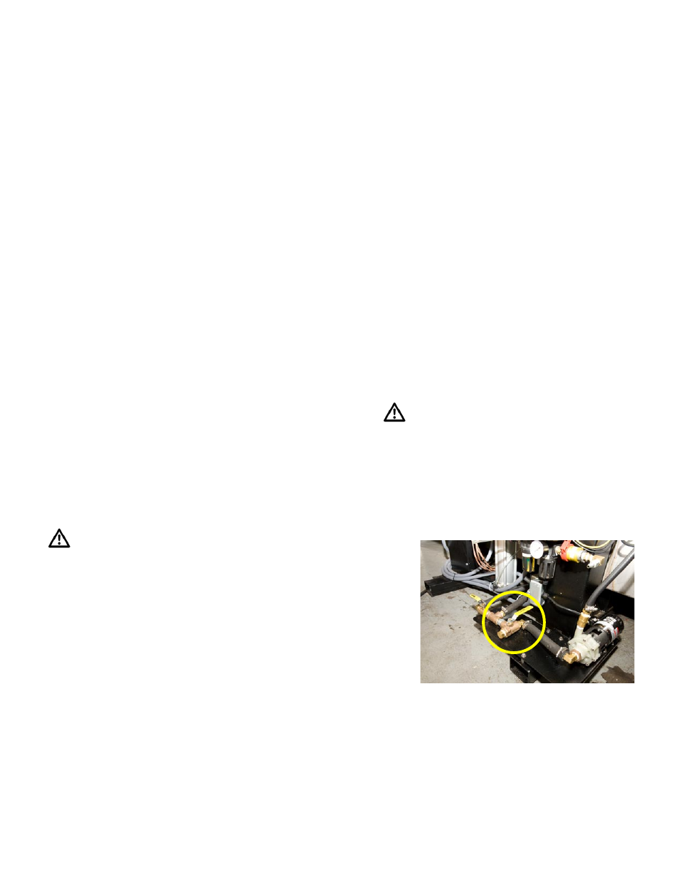
5. Fill the main tank and weir chamber as follows:
a) Close ball valve between drain lines from
main Tank and weir chamber.
(Figure 1 – Valve Setting)
b) Set 3-way ball valve to permit flow from
drain hoses to pump (shown in closed
position above in Figure 1).