B. hook-up, C. internal wiring, D. thermostat – Comfort-Aire TGRG Series for R-410A User Manual
Page 24
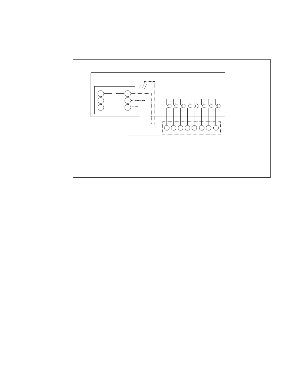
B. HOOK-UP
To wire unit, refer to the following hook-up diagram (see Figure 21).
Refer to Figure 1 for location of wiring entrances.
Wiring to be done in the field between the unit and devices not attached to the unit, or
between separate devices which are field installed and located, shall conform with the
temperature limitation for Type T wire [63°F rise (35°C)] when installed in accordance
with the manufacturer’s instructions.
C. INTERNAL WIRING
IMPORTANT: Some single phase units are equipped with a single pole contactor.
Caution must be exercised when servicing as only one leg of the power supply is broken
with the contactor.
A diagram of the internal wiring of this unit is located under the electrical box cover and
in this manual. If any of the original wire as supplied with the appliance must be
replaced, the wire gauge and insulation must be same as original wiring.
Transformer is factory wired for 230 volts on 208/230 volt models and must be changed
for 208 volt applications. See unit wiring diagram for 208 volt wiring.
D. THERMOSTAT
The room thermostat must be compatible with the spark ignition control on the unit.
Generally, all thermostats that are not of the “current robbing” type are compatible with
the integrated furnace control. Two stage units (5 ton) require use of a thermostat capa-
ble of 2 stages of cooling. (See Section IV.) See chart below for recommendations. The
low voltage wiring should be sized as shown in Table 6.
Install the room thermostat in accordance with the instruction sheet packed in the box
with the thermostat. Never install the thermostat on an outside wall or where it will be
influenced by drafts, concealed hot or cold water pipes or ducts, lighting fixtures, radia-
tion from fireplace, sun rays, lamps, televisions, radios or air streams from registers.
Refer to instructions packed with the thermostat for “heater” selection or adjustment.
FOR INTERNAL WIRING SEE WIRING LABEL ATTACHED TO UNIT
*
T1
T2
T3
L1
L2
L3
CONTACTOR
HIGH VOLTAGE
DISCONNECT
SWITCH
CHASSIS GROUND
THERMOSTAT
Y - COOLING (LOW STAGE IN 2 STAGE SYSTEMS)
G - FAN ONLY
R - 24V
W - HEATING
C - COMMON
Y2 - HIGH STAGE COOLING (TWO STAGE ONLY)
L - ALERT CODES (OPTIONAL WITH COMFORT ALERT
L -
AND COMPATIBLE THERMOSTAT)
ODD - ON-DEMAND DEHUMIDIFICATION
*L2 connection 3Phase only
LOW VOLTAGE
WIRE LEADS
Y
G
R
W
C
Y2
L
Y
G
R
W
C
Y2
L
ODD
ODD
FIGURE 21
WIRE HOOK-UP DIAGRAM
24