Outdoor unit installation, Condensate drainage – Comfort-Aire VMH 24 SD User Manual
Page 9
9
Heat Controller
VMH 09/12/18/24 SD Inverter Mini-Split
Outdoor Unit Installation
• Install the outdoor unit on a rigid base such a
concrete slab to prevent increasing noise level and
vibration.
• Use a raised concrete pad or concrete blocks to
provide a solid, level surface. Securely anchor the
unit down with bolts.
• In a snowy area, slab should be higher than drifting
snow.
• See outdoor installation location information on page.
4 for more details and acquired clearances.
Anchoring outdoor unit
Anchor the outdoor unit to the concrete slab with lag
bolts or similiar size, may vary by model.
NOTE: Lag bolts are field provided and do not come
with the unit.
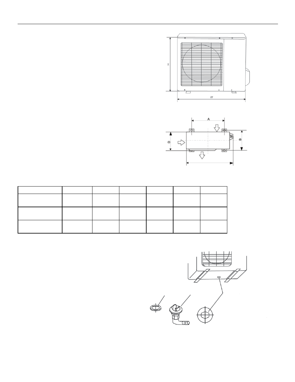
Refer to unit’s mounting footprint for mounting hole
locations A & B. (Fig. 18)
Condensate Drainage
• For heat pump models only.
• Condensate and defrosted water, created by the
unit operating in heat mode, should be routed
and drained away from the unit.
• Fit the seal onto the drain elbow, then insert the
drain elbow into the hole on the base pan of the
outdoor unit, rotate it 90° to secure into place.
(Fig. 19)
• Connect a locally purchased drain and insulated
hose to the hose barb end of the elbow.
• Route the hose to drain location away from
the unit.
Note:
Some models may have more then one drain hole in
the base of the unit.
Base pan hole of
outdoor unit
Fig. 18
Fig. 19
Model
W
H
D
W1
A
B
VMH 09
VMH 12
29.9 in.
(760 mm)
11.2 in.
(285 mm)
23.2 in.
(590 mm)
32.4 in.
(823 mm)
20.9 in.
(530 mm)
11.4 in.
(290 mm)
VMH18
33.3 in.
(845 mm)
12.6 in.
(320 mm)
27.6 in.
(700 mm)
35.7 in.
(908 mm)
22.0 in.
(560 mm)
13.2 in.
(335 mm)
VMH 24
36.7 in.
(900 mm)
12.9 in.
(315 mm)
35.1 in.
(860 mm)
40 in.
(980 mm)
24.1 in.
(590 mm)
13.6 in.
(333 mm)
Seal
Drain elbow
Air inlet
Air inlet
Air outlet
W1