I n s ta l l at i o n, Pag e 5 – Australian Monitor DPRM User Manual
Page 5
D P R M I N S TA L L AT I O N & O P E R AT I O N M A N UA L
PAG E 5
I N S TA L L AT I O N
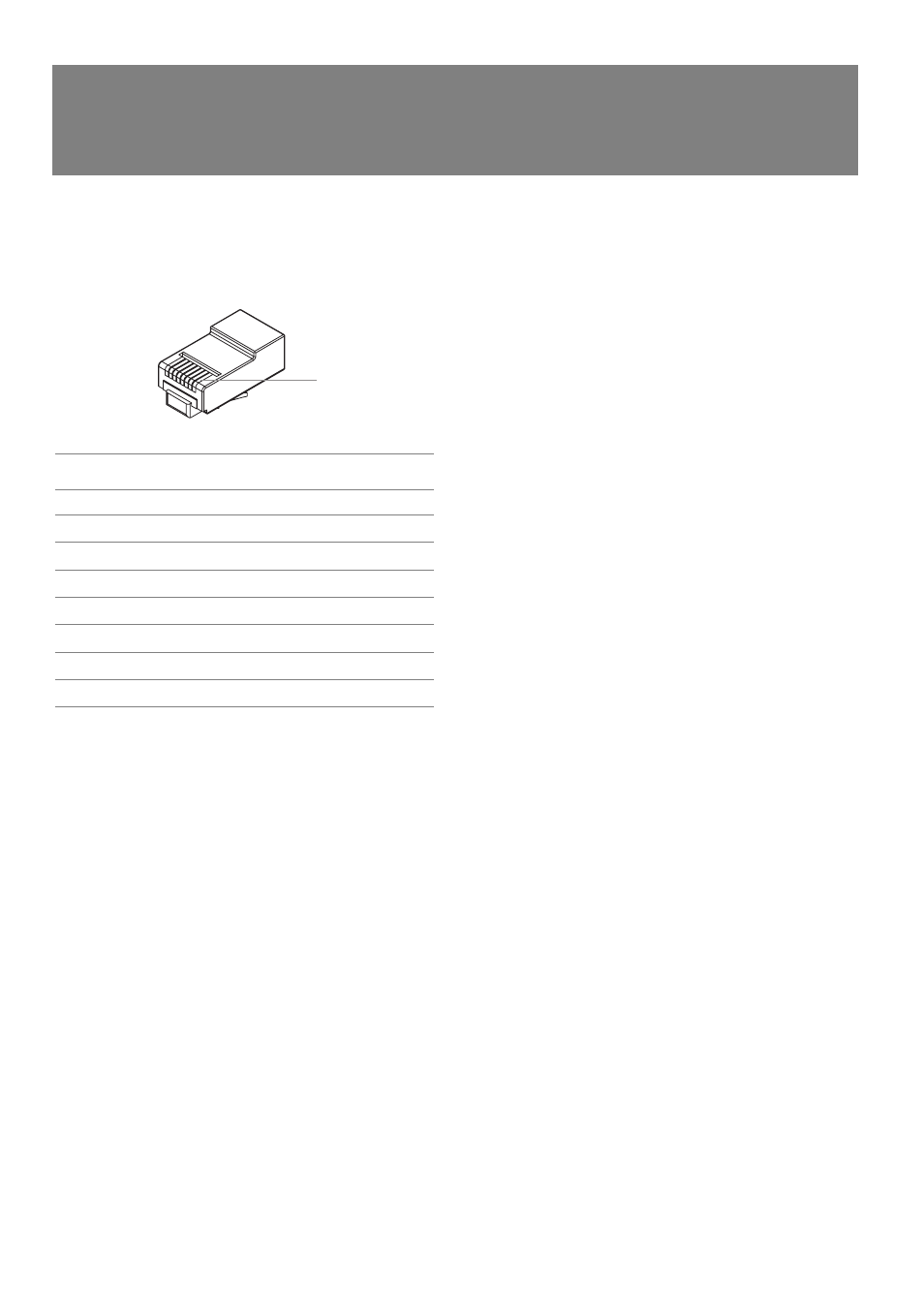
The CAT5 cable connects to the screw terminals numbered 1-6. These
numbers correspond to the pins of the RJ45 connector on the main
unit. If following the 568A convention, the wire colours are wired as:
P I N
W I R E C O L O U R
D P N E T W O R K
1
White/Green
Ground
2
Green
+18V
3
White/Orange
Data+
4
Blue
Busy-
5
White/Blue
Busy+ (+18V)
6
Orange
Data-
7
White/Brown
Spare
8
Brown
Spare
Ensure that the spare pair cannot short to anything.
NOTE: If the Remote Control Panel is NOT the last
unit in the CAT5 RUN and there are paging stations
connected further down the run it is important that
the spare pair is continued to the next unit otherwise
voice information from the paging stations will not
get to the main DigiPage unit.
There are two holes available adjacent to the terminal block for
securing the CAT5 cable with a cable tie.
“PIN 1”
☛