Audiovox PROV 710 P User Manual
Page 8
-6-
PROV710/ PROV710 S/ PROV710 P
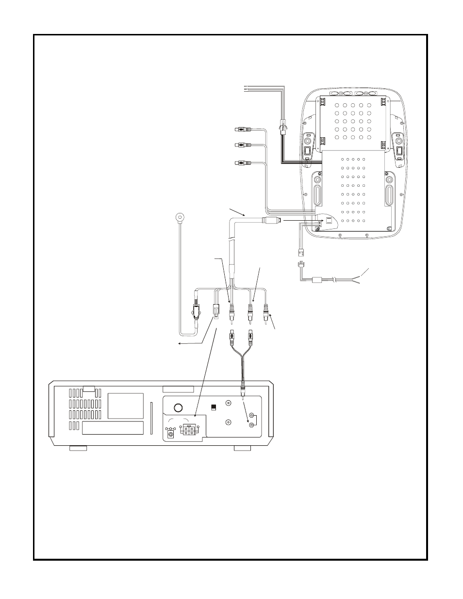
1) Connect the Circular Mini-Din Connector of the source Component Harness into the 8 pin Din
Connector on the unit.
2) Connect the Power Harness to the mating connector on the Video Monitor.
3) Connect the power harness to the vehicle’s electrical system through an In-Line 5-Ampere fuse by
tapping into an accessory hot line.
4) Verify all functions of the System before final mounting of the finished assembly.
Pow er H arness
item # 3
R ed: + 12VD C
Accessory C kt.
(Install
5A
Inline Fuse)
B l
ack: G round
RC A M ALE
C O N N EC TO R
VID EO IN (YELLO W )
R C A M ALE
C O N N EC TO R
AU D IO IN (W H ITE)
RC A M ALE
C O N N EC TO R
AU D IO IN (R ED )
Pow er
C onnector 4 Pi
n
IR LED :
C l
ean the IR R eceiver W i
ndow on the front of the VC P.
Rem ove Adhesive Backing and Apply IR LED to IR
W indow on the Face of the VC P.
“Y” Adapter
for use w i
th
N on-Stereo
Instal
lati
ons
AN T.
IN
RF
O U T
O UT
FU SE
DC
IN
Accessory
H arness
item # 2
Red/B lack (Lam p O n)
Violet/Brow n (Lam p Auto)
B lack/Red (Lam p C om m on)
RC A FEM ALE
CO NN ECTO R
VI
D EO
O U T
(YELLO W )
RC A
FEM ALE
CO NN EC TO R
AU DI
O O UT
LEFT (W HITE)
RC A FEM ALE
CO NN ECTO R
AU DIO O UT
RI
G H T
(RED)
D om e Li
ght H arness
item # 5