Amtrol OWB Series User Manual
Page 13
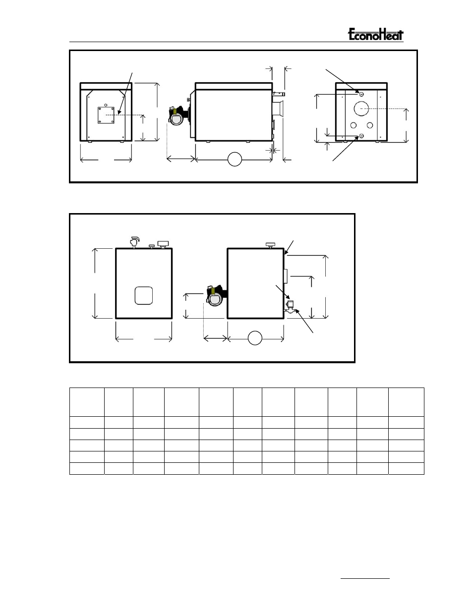
2-1/2 M.P.T. Supply Connection
9-3/8”
Centerline Of Burner Plate
36”
29-1/2”
20”
17”
4”
2-1/2 F.P.T. Return Connection
3/4”
L
8”
33”
Approx. 14”
OWB-35 and OWB-50 Specifications
1-1/2” Supply Connection
Circulator
26”
21-1/2”
15-1/2”
12-1/4”
1-1/2”
Return
Connection
L
25”
Approx. 14”
OWB-9, OWB-15, and OWB-25 Specifications
Boiler
Model
Burner
GPH
Input
BTU’s
Output
Capacity
BTU’s
NET
Rating
Water
BTU/HR.
NET
Rating
Water
SQ.FT.
Approx.
Dry
Weight
Lbs.
Vent
Connect
Dia.
Inches
Dim
“L”
Inches
Water
Content
Gal.
Max.
Water
Working
Pressure
OWB-9
.60
90,000
76,500
66,500
522 527 7 24-1/4
5.5 60PSI
OWB-15
1.0
150,000
127,500
110,800
875 716
7 34-1/4
8.2 60PSI
OWB-25 1.7 250,000
212,500
184,700
1,450 902
7 44-1/4 10.8 60PSI
OWB-35 2.4 350,000
297,500
258,600
2,030 1654
10
52 28.5 75PSI
OWB-50 3.3 500,000
425,000
369,500
2,900 1831
10
57 31.7 75PSI
Table 1.
NOTES:
1. Net ratings shown are based on a piping and pick-up allowance of 1.15.
2. Net ratings in sq. ft. are based on 170 deg F average water temperature in radiators. For
higher water temperatures, select boiler on basis of net ratings in BTU/HR.
3. Firing rate in G.P.H. is based on oil having heat value of 150,000 BTU/GAL.
4. 4% reduction of output for every 1,000 ft. of elevation.
Installation, Operation, And Service Instructions
13