Pathway Programmable Relay Driver -# LCRD16 User Manual
Lcrd16 relay driver, Configuration, Connector legend
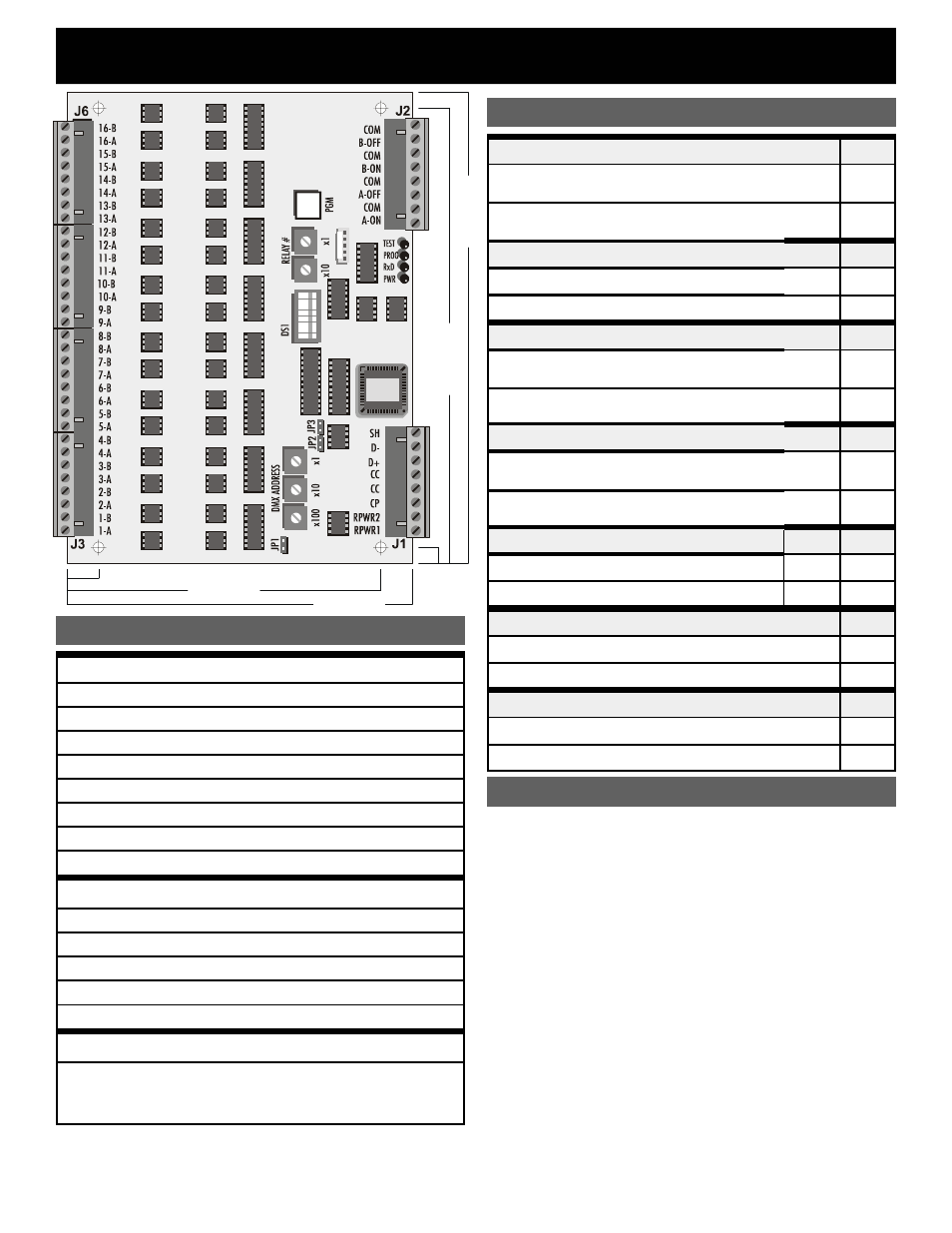
LCRD16 RELAY DRIVER
CONNECTOR J1
RPWR1 Relay Coil Power Supply (Hot), 24VAC
RPRW2 Relay Coil Power Supply (Neut.), 24VAC
CP
Control Power Supply 12-24VAC or DC(+) 200mA
CC
Control power supply common
CC
Control power supply common
D+
DMX512 Data +
D-
DMX512 Data -
SH
DMX512 Shield
CONNECTOR J2
A-ON
Master Switch “A“ input, momentary ON
A-OFF
Master Switch “A” input, momentary OFF
B-ON
Master Switch “B” input, momentary ON
B-OFF
Master Switch “B” input, momentary OFF
COM
Master Switch common (4 positions)
CONNECTOR J3-J6
1A/B
thru
16A/B
Relay coil drive outputs, one coil drive wire each for
momentary polarized pulse-latching relays and AC
maintained coil relays (“A” lead); one coil common
wire per relay (“B” lead)
CONNECTOR LEGEND
NOTE: Relay coil drive maximum rating 300mA continuous, 3A
surge (inrush). Use a pilot relay for higher current requirements.
RELAY TYPE
DS-1
Momentary: Outputs a 100ms polarized DC pulse
for 2-wire latching relays
ON
Maintained: Outputs a constant AC voltage for
maintained relays
OFF
THRESHOLD SELECT
DS-2
25% Threshold (on at 30%, off at 20%)
ON
75% Threshold (on at 80%, off at 70%)
OFF
OUTPUT SCAN MODE
DS-3
Scan Mode Enabled:
Turns relays on or off in sequence, 10 per second
ON
Scan Mode Disabled:
Turns relays on or off simultaneously
OFF
CONTROL MODE
DS-4
Patch:
Addressing determined by user programmed patch
ON
Offset:
Addressing determined by address select switches
OFF
PROGRAM MASTER SWITCH
DS-5
DS-6
Program Master Switch “A”
ON
OFF
Program Master Switch “B”
OFF
ON
PROGRAM MODE
DS-7
Program Mode Enabled
ON
Program Mode Disabled
OFF
TEST MODE
DS-8
Test Mode enabled
ON
Normal (Run) Mode
OFF
DIP Switch Settings
DS-7 must be OFF and DS-8 ON. The “TEST” LED will
be on.
Relay Test Function: DS-4 must be off. The DMX
address switches select the relay number to test. The
selected relay can then be turned on by pressing the
program pushbutton. If the number is out of the correct
range (000 to 016 in momentary mode) the "TEST" LED
will flash to indicate an error when the button is pressed.
DMX Test Function: The DMX receive LED (RxD) will
be on and steady if a valid DMX signal is received. If no
DMX signal is present the LED will be off. If the DMX
signal is not valid the LED will flash continuously.
Patch Testing Mode: DS-4 must be on. The address
switches select the DMX channel #. When the program
pushbutton is pressed, relays assigned to that DMX
channel # will turn ON. When the pushbutton is released
those relays will turn OFF. The "TEST" LED will flash
once if there is an error in the address range selection.
TEST MODE
Configuration
PROGRAMMABLE WITH
MASTER SWITCH INPUTS
0.5000"
5.0000"
5.5000"
0
.25
00
"
7
.25
00
"
7
.50
00
"