Fagor FA2532 User Manual
Page 32
D
DE
ES
SC
CR
RIIP
PT
TIIO
ON
N O
OF
F Y
YO
OU
UR
R A
AP
PP
PL
LIIA
AN
NC
CE
E
((d
de
ep
pe
en
nd
diin
ng
g o
on
n tth
he
e m
mo
od
de
ell))
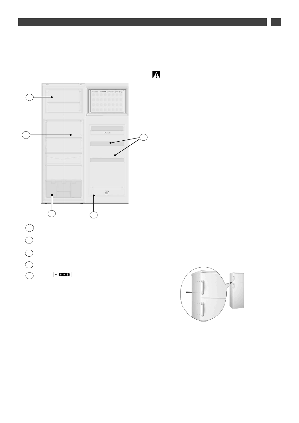
Freezer compartment
1
1 /
/ INSTALLATION
EN
IIR
RE
EV
VE
ER
RS
SIIN
NG
G T
TH
HE
E D
DIIR
RE
EC
CT
TIIO
ON
N T
TH
HE
E D
DO
OO
OR
RS
S
O
OP
PE
EN
N
You can alter the direction in which the doors open if you wish:
T
Th
he
e a
ap
pp
plliia
an
nc
ce
e m
mu
us
stt a
allw
wa
ay
ys
s b
be
e d
diis
sc
co
on
nn
ne
ec
ctte
ed
d ffrro
om
m tth
he
e p
po
ow
we
err
s
su
up
pp
plly
y w
wh
he
en
n c
ch
ha
an
ng
giin
ng
g tth
he
e d
diirre
ec
cttiio
on
n tth
he
e d
do
oo
orrs
s o
op
pe
en
n..
• Tilt the appliance slightly backwards and wedge it in this position.
•Unscrew the [pin from the lower hinge and then remove the door
from the refrigerator section.
•Take off the lower hinge by removing the 4 screws.
Fit it on the opposite side.
•Unscrew the middle hinge and remove the freezer door.
•Remove the upper hinge and fit it on the opposite side
•Swap over the hole covers and the plastic hinge pin guides on the
top of both doors.
•Fit and hold the freezer door on its hinge pin, insert the middle
hinge into the lower part of the door and screw it in place.
•Insert the refrigerator door between the middle hinge and the bot-
tom hinge and then close it.
•Refit the lower hinge and screw it firmly in place.
•If your appliance is fitted with a vertical handle, remember to move
it to the opposite side.
0
04
4
Thermostat
Door shelves
Vegetable compartment
Bottle shelf
F
F
IIT
TT
TIIN
NG
G T
TH
HE
E D
DO
OO
OR
R H
HA
AN
ND
DL
LE
ES
S
((d
de
ep
pe
en
nd
diin
ng
g o
on
n tth
he
e m
mo
od
de
ell))
The handles are located inside the refrigerator. Fit the handles on
the doors, positioning them opposite the respective holes and fas-
ten them with the screws provided as shown in the diagram below.
Once the handles are in place, insert the screw covers supplied in
the spaces provided for this purpose
C
D
E
B
A
A
A
A
C
C
D
D
B
B
E
E
A
A
B
B
C
C
D
D
E
E