Agilent Technologies Logic DDR2 Dimm High Speed Pro FS2334 User Manual
Page 10
10
FS2334 Frontside layout
FS2334 Backside layout
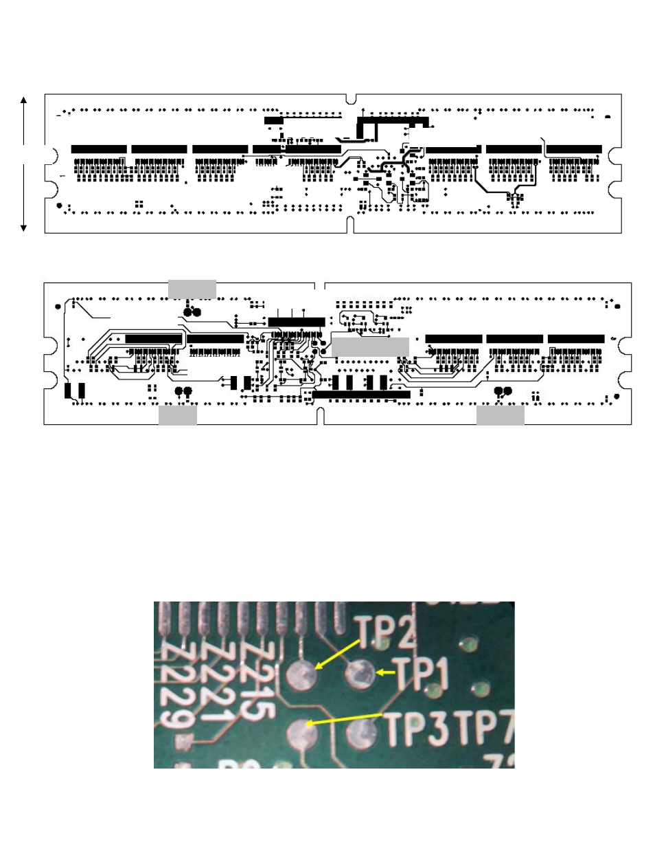
Test Points
There are several test point on the board.
The first set of test points are used to select which signals go to the Clk input and the
D15 input of Header 2. The shipping configuration for the FS2334 is to have S0 wired to
the Clk input, which is TP3 wired to TP1. This is done in the factory by soldering a short
wire between the 2 test points.
If CKE0 is to be used as a Clk input then TP7 is wired to TP1 and S0 is brought to the
D15 input by wiring TP3 to TP2.
Header 3
Header 4
Header 5
Header 14
Header 1
Header 6
Header 7
Header 8
Header 13
Header 9
Header 2
Header 11
Header 10
Header 12
TP 5
TP 6
TP 4
TP 1,2,3,7
1.25”