COOK CBF User Manual
Installation, operation, and maintenance manual
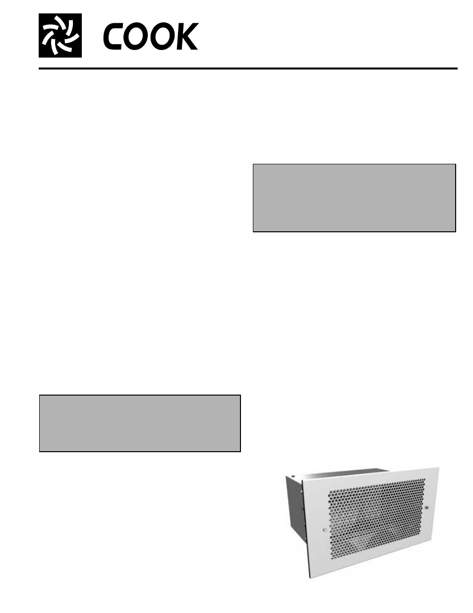
CBF
Cinder Block Fan
INSTALLATION, OPERATION, AND MAINTENANCE MANUAL
This publication contains the installation, operation
and maintenance procedures for standard units of the
CBF - Cinder Block Fan. Carefully read this publication
prior to installation.
Loren Cook catalog, CBF, provides additional information
describing the equipment, fan performance, available
accessories and specification data.
For additional safety information, refer to AMCA publica-
tion 410-96, Safety Practices for Users and Installers of
Industrial and Commercial Fans.
All of the publications listed above can be obtained from
Loren Cook Company by phoning (417) 869-6474, exten-
sion 166; by FAX at (417) 832-9431; or by e-mail at
[email protected].
For information and instructions on special equipment,
contact Loren Cook Company at (417) 869-6474.
Receiving and Inspection
Carefully inspect the fan and accessories for any dam-
age and shortage immediately upon receipt of the fan.
• Turn the wheel by hand to ensure it turns freely and
does not bind.
• Remove shipping tape.
• Record on the Delivery Receipt any visible sign of
damage.
Handling
Lift fan by the outside housing (box). Never lift by the
shaft or motor.
Storage
If the fan is stored for any length of time prior to installa-
tion, store it in its original shipping crate and protect it from
dust, debris and the weather.
Installation
CBF units are intended to replace an 8”x16” standard cin-
der block in a block wall. Slide unit into open block location,
as desired, and screw into place using pre-punched holes
in the front flange. After unit is installed and wired, attach
grille using the two screws provided.
WARNING
This unit has rotating parts. Safety precautions
should be exercised at all times during installation,
operation, and maintenance.
ALWAYS disconnect power prior to working on fan.
CBF
Wiring Installation
All wiring should be in accordance with local ordinances
and the National Electrical Code, NFPA 70. Ensure the
power supply (voltage, frequency, and current carrying
capacity of wires) is in accordance with the motor name-
plate.
Lock off all power sources before unit is wired to
power source.
Follow the wiring diagram in the disconnect switch
and the wiring diagram provided with the motor. Cor-
rectly label the circuit on the main power box and
always identify a closed switch to promote safety (i.e.,
red tape over a closed switch).
Final Installation Steps
a. Inspect fasteners and setscrews, particularly fan mount-
ing fasteners, and tighten.
b. Inspect for correct amperage and voltage with an
ammeter and voltmeter.
c. Ensure all accessories are installed.
d. Make sure wheel does not rub against the inlet.
Operation
Pre-Start Checks
a. Lock out all the primary and secondary power sources.
b. Inspect fasteners and setscrews, particularly those used
for mounting the fan, and tighten if necessary.
c. Inspect motor wiring.
d. Ensure fan and ductwork are clean and free of debris.
e. Restore power to unit.
Personal Safety
Disconnect switches are recommended. Place the
disconnect switch near the fan in order that the
power can be swiftly cut off in case of an emer-
gency, and in order that maintenance personnel are
provided complete control of the power source.