Gx2411ci, Owner’s man, English version – Audiovox GX2411ci User Manual
Page 11: Mounting position
GX2411ci English I/B ver. 09010A-1
09010A-1
10
OWNER’S MAN #
GX2411ci
VER. 09010A-1
PAGE:
10
English version
Two Way Recording(s) or to stop the current activity.
8.
ERASE Button: Press to erase a single message or all messages in order to
conserve message space in memory.
9.
MEMO PLAY Button: Press to playback the Memo message(s).
10.
ANS. ON/OFF Button: Press to activate or deactivate answer function.
11.
(Skip) Button: Press to skip to the next message during playback.
12.
OGM PLAY Button: Press to playback Outgoing Message (OGM).
13.
(Previous) Button: Press to skip to the previous message during playback.
14.
PAGE / 2-WAY REC Button: Also allows you to locate the handset when it is not on
the base or record two way conversation.
15.
NEW CALL LED Indicator: Flashes rapidly if the system has new call message(s)
and have message(s) in your voice mailbox
16.
MEMO LED Indicator: Lights up to indicate the presence of Memo message and
blinks if there are new Memo message(s).
17.
MSG LED Indicator: Lights up to indicate the presence of Incoming Message (ICM)
and Two-Way Recordings. Blinks if there are new Incoming Message(s) (ICM) or
Two-Way Recording(s).
18.
CHG (Charge) / IN USE LED Indicator: Lights up steadily when the phone is being
used and when the handset is being charged on the base .
19.
Digital LED Display: A two-digit LED display to indicate the number of Incoming
Message(s) and Two-Way Recording(s). Also displays the system status and the
current channel number while in TALK mode.
Code
Function
00-59
Message / Timer count / Channel No.
--
Answering OFF
Ir
Memo Recording
2r
Two-Way Recording
An
Answering Mode
rc
Remote Control
FU
Memory Full
ER
Erasing Message
OP
OGM Playback
Or
OGM Recording
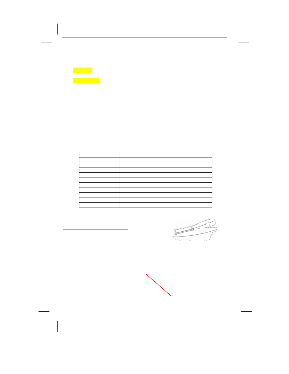
20. Retainer Tab: Allows the handset to hang on the base unit at wall mount position.
MOUNTING POSITION
DESKTOP USE:
Connect the telephone line cord to the TEL LINE jack on
the rear of the base unit and connect the opposite end to
the telephone modular jack. ( Figure 4)
WALL USE :
A. WITH A STANDARD AT&T OR GTE MODULAR WALL JACK
1.
Install the wall mount bracket at the position as shown in Figure 5.
Telephone Modular
Wall Jack