Optional adaptors, Video input adaptor bkm-fw10, Rgb/component active through adaptor bkm-fw12 – Sony KLH-W26 User Manual
Page 41
9
GB
GB
Optional Adaptors
The connectors marked with 4 on the side panel are
slot-in type and can be installed with any of the
optional adaptors (not supplied).
For details on installation, consult your Sony dealers.
VIDEO INPUT Adaptor BKM-FW10
1
S VIDEO IN (Mini DIN 4-pin): Connects to the
S Video signal output of a piece of video
equipment.
2
S VIDEO OUT (Mini DIN 4-pin): Connects to
the S Video signal input of a piece of video
equipment.
3
VIDEO IN (BNC): Connects to the video signal
output of a piece of video equipment.
4
VIDEO OUT (BNC): Connects to the video
signal input of a piece of video equipment.
5
AUDIO IN L/R (Pin jack): Connects to the audio
output of a piece of video equipment.
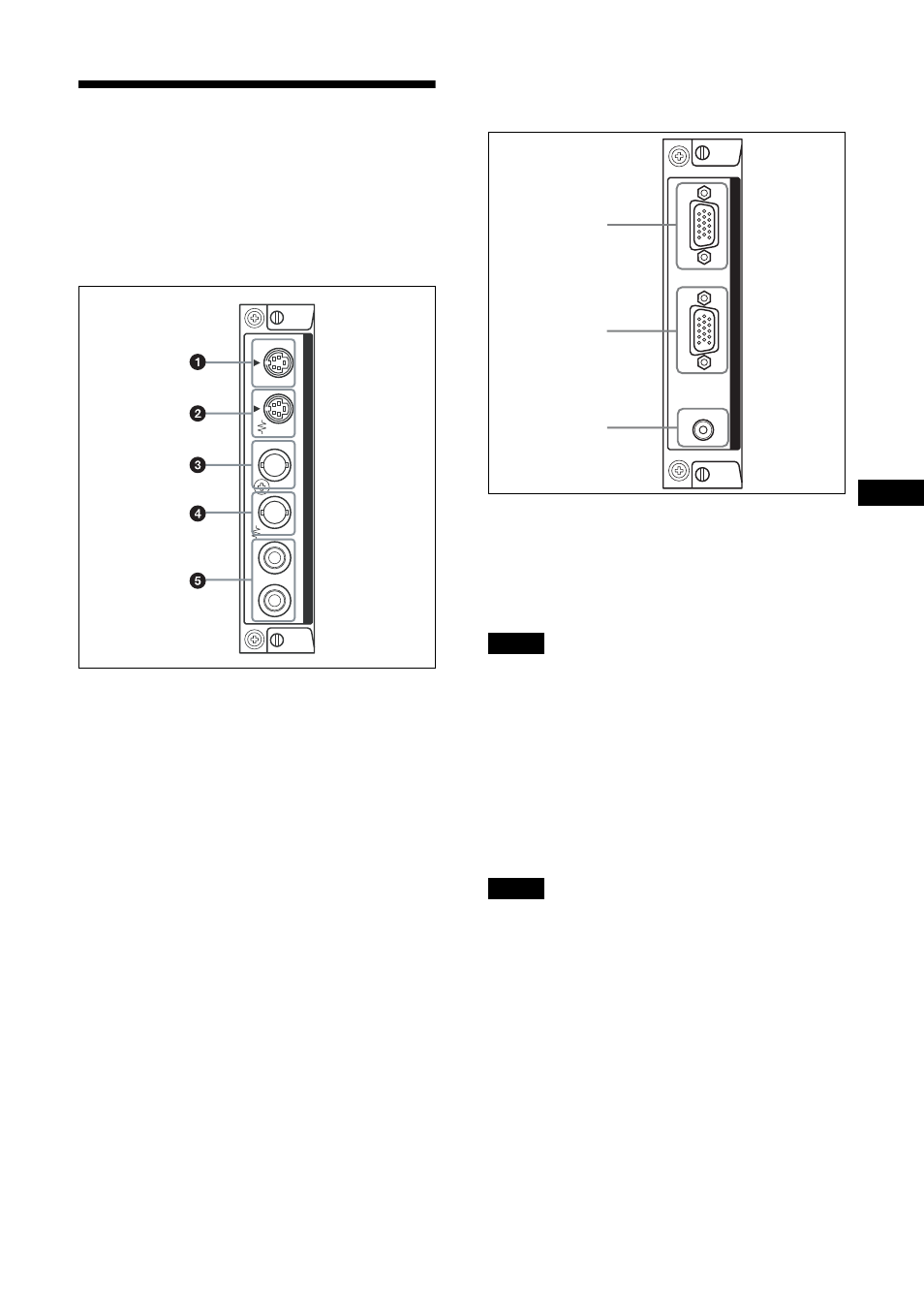
RGB/COMPONENT ACTIVE THROUGH
Adaptor BKM-FW12
1
RGB/COMPONENT IN (D-sub 15-pin):
Connects to the component signal output or
analog RGB signal output of a piece of video
equipment or PC. For details on inputting a
component signal to the connector, see Pin
assignment on page 29 .
When inputting a component signal, be sure not to input sync
signals to pins 13 and 14. If you do so, the picture may not be
displayed properly.
2
RGB/COMPONENT OUT (D-sub 15-pin):
Connects to the component signal input or analog
RGB signal input of a piece of video equipment or
PC.
3
AUDIO IN (Stereo mini jack):
Inputs an audio signal. Connects to the audio
signal output of a piece of video equipment or PC.
When the display is not connected to an AC power or is in
the standby mode, no signal is output from the RGB/
COMPONENT OUT.
For details on the optional adaptors for system
expansion, BKM-FW series, see each instruction
manual.
VIDEO
S VIDEO
IN
OUT
IN
OUT
RL
AU
D
IO
I
N
VIDEO INPUT AD
APT
OR
Note
Note
AU
D
IO
IN
OUT
IN
RGB/COMPONENT A
CTIVE
THR
OUGH
1
2
3