Nalog, Udio, Alanced – ALESIS ADAT-XT User Manual
Page 28: Nputs and, Utputs
Chapter 3: Connections
24
ADAT XT Reference Manual
A
NALOG
A
UDIO
– B
ALANCED
I
NPUTS AND
O
UTPUTS
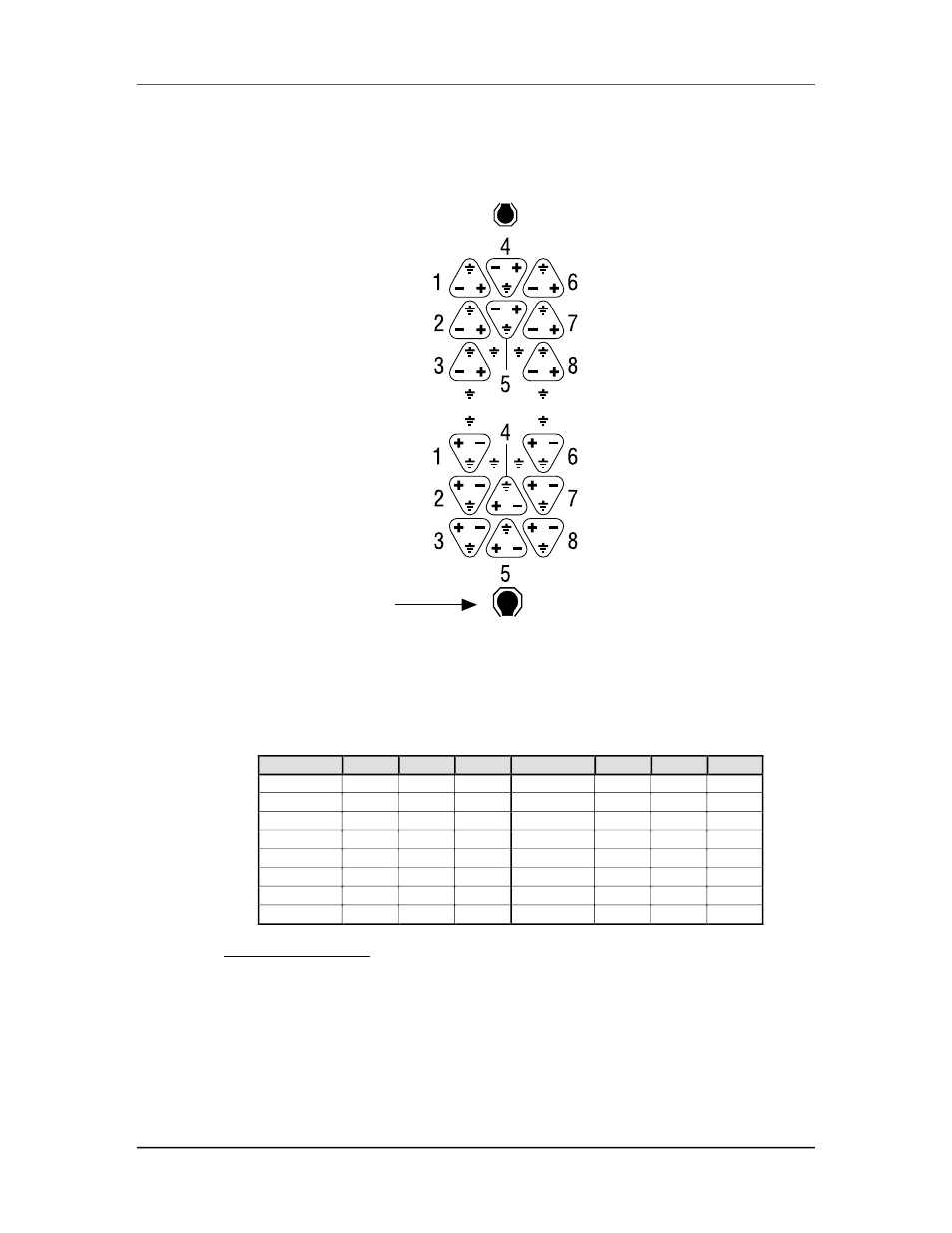
The +4 dBu balanced line inputs and outputs use an ELCO® multipin connector. The
balanced in/out connector wiring scheme is as follows:
Larger Key Notch
INPUTS
OUTPUTS
Note: The larger of the two outer key notches is at the bottom.
J
Both the unbalanced and balanced inputs and outputs may be used simultaneously.
Pin out letters are referenced to the alphabetical designation on a standard 56-pin
ELCO connector.
Channel
GND
NEG
POS
Channel
GND
NEG
POS
In 1
NN
JJ
HH
Out 1
Z
c
d
In 2
CC
y
x
Out 2
P
U
V
In 3
t
n
m
Out 3
D
J
K
In 4
FF
MM
LL
Out 4
T
M
N
In 5
w
BB
AA
Out 5
H
B
C
In 6
KK
EE
DD
Out 6
W
a
b
In 7
z
v
u
Out 7
L
R
S
In 8
p
l
k
Out 8
A
E
F
Additional grounds:
r, s, h, j, e, f, X, and Y.
®ELCO is a registered trademark of Elco Corporation - a Kyocera Group Company