Screw and hook locations diagram/table, Tv installation dimensions table – Sony KDL-52WL135 User Manual
Page 2
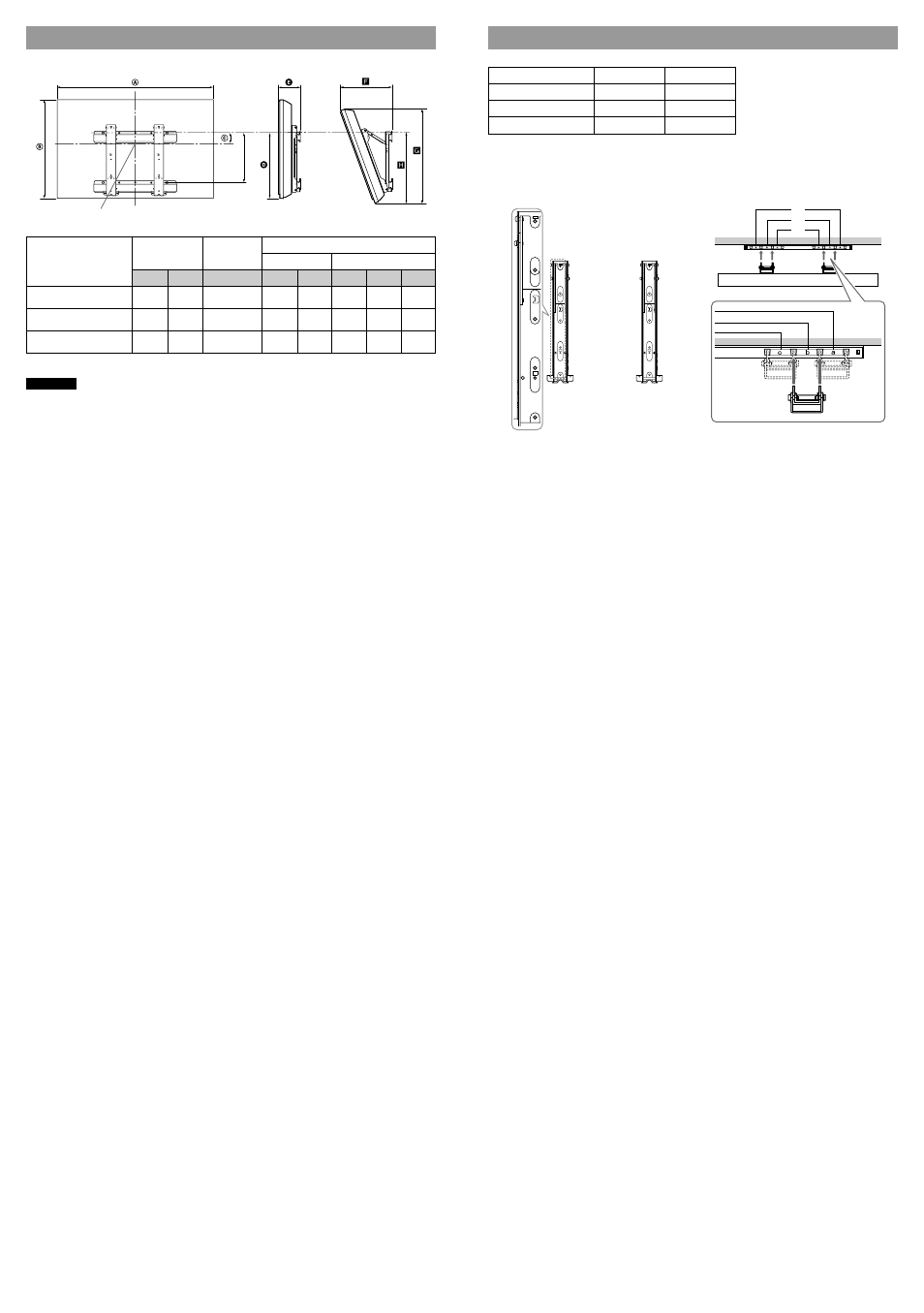
Screw and Hook locations diagram/table
Model Name
Screw location
Hook location
KDL-40WL135
e, g
b
KDL-46WL135
e, g
b
KDL-52WL135
d, g
a
* Hook position “c” cannot be used for the models in the table above.
Screw location
When installing the Mounting Hook on the TV.
Hook location
When installing the TV onto the Base Bracket.
h
j
g
f
e
d
h
j
g
f
e
d
h
j
g
f
e
d
a
b
c*
TV installation dimensions table
Screen center point
320 (12
5
/
8
)
Display
Screen center
Length for each mounting angle
Model Name
dimensions
dimensions
Angle (0˚)
Angle (20˚)
A
B
C
D
E
F
G
H
KDL-40WL135
992
643
176
518
182
345
620
557
(39
1
/
8
)
(25
3
/
8
)
(7)
(20
1
/
2
)
(7
1
/
4
)
(13
5
/
8
)
(24
1
/
2
)
(22)
KDL-46WL135
1135
734
128
519
182
376
706
558
(44
3
/
4
)
(29)
(5
1
/
8
)
(20
1
/
2
)
(7
1
/
4
)
(14
7
/
8
)
(27
7
/
8
)
(22)
KDL-52WL135
1278
832
73
519
183
410
797
555
(50
3
/
8
)
(32
7
/
8
)
(2
7
/
8
)
(20
1
/
2
)
(7
1
/
4
)
(16
1
/
4
)
(31
1
/
2
)
(21
7
/
8
)
Unit: mm (inches)
Figures in the above table may differ slightly depending on the installation.
WARNING
The wall that the TV will be installed on should be capable of supporting a weight of at least four times that of
the TV. Refer to your TV’s instructions for its weight.