Figure 8 – Allied Air Enterprises (2 User Manual
Page 10
Page 10 of 13
506252-01
Issue 0902
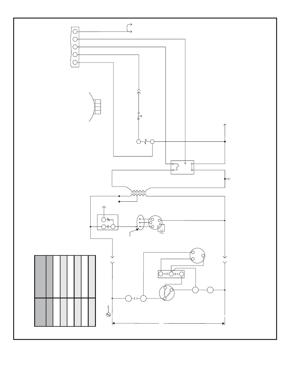
Figure 8
Connection Diagram
Single Phase – PSC Motor
P/N 48396-001
Unit
F
ac
tor
y
S
hipped
S
e
tti
n
g
s
C
ooling
Input
(B
L
K
)
24
LO
W
30
MED
36
HIGH
42
LO
W
48
MED
60
HIGH
BLOWER SPEED CHAR
T
208/230V
-1-60
G
W1
C
R
BLK
RED
YEL
RED
CONT
A
CT
OR
THERMOST
A
T
L1
T1
T2
L2
C
H
F
CONDENSER
F
AN MO
T
OR
COMPRESSOR
CONT
A
CT
OR
COMPRESSOR
CONT
A
CT
OR
DU
AL
CAP
A
CIT
OR
COMPRESSOR
TRANSFORMER
C
S
R
WHT
L2
L1
BLK
BRN
PUR
RED
RED
BLK
208V
240V
24V
INDOOR
BLO
WER
M
OTO
R
S1
K1
T1
B3
B4
K1-2
C12
B1
K1-1
BLU
YEL
C4
CAP
A
CIT
OR
H
M
L
C
SEE CHAR
T
FOR
WIRING
NO
NC
C
BLO
WER
CONTR
OL
A15
BLK
C
G
XFMR-R
R
XFMR-C
FUSE
Y
A15
BLO
WER
GRN
RED
BLU
BLU
YEL
BLU
BLK
BLK
WHT
P-1
P-2
P-4
P-6
P-5
BLU
YEL
YEL
HIGH PRESSURE
SWITCH
(IF USED)
S4
GRN
RED
YEL
P-3
BLU
L
M
OTO
R
SPEED
T
APS
C
H
M
CONTR
OL
NO
TE - If an
y of the or
iginal wire is replaced, the same siz
e and type wire m
ust be used.
Use copper conductor only
, min.
75°C wire
.
W
ARNING - Electr
ic shoc
k hazard.
Unit m
ust be g
rounded in accordance with national and local codes
.
Line v
oltage field installed.
W1 &
W2 can be used to stage electr
ic heat accessor
y on 15 & 20kW models
.
5, 7.5, & 10kW heater accessor
ies function off
W1 only
.