American Dynamics 1461 User Manual
Page 6
CONNECTIONS
60HZ
0
C O N T R O L
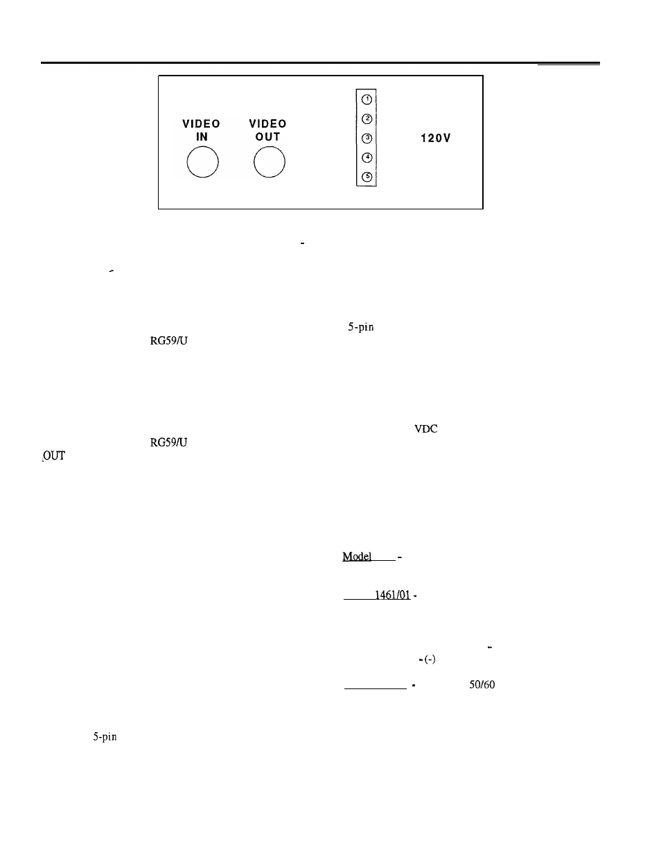
Figure 2 1461 Rear Panel
CONNECTIONS
Video Input
Auxiliary Start Relay Connections
The
CONTROL connector is also used to access a
Connect a good grade of
video cable from the camera
normally open, SPST relay which can be used to activate a
to the VIDEO IN BNC Connector on the rear panel of the
VCR or other devices during an alert. The relay contacts
1461. The 1461 has a passive loop-thru input. It does not
provide a closure between pins 3 and 4 when an alert condition
terminate the input in 75 ohms. The video input cable should
occurs. CAUTION: DO NOT USE THIS RELAY TO
be terminated in 75 ohms at the end of the run.
SWITCH LINE VOLTAGES. The relay contact ratings are:
Video Output
Connect a good grade of
video cable from the VIDEO
BNC connector on the rear panel of the 1461 to the video
input of the monitor or video switcher. This cable should be
terminated in 75 ohms, or if looped thru the monitor or
switcher, terminated at the end of the run.
.
Automatic Switcher Call-Up Connections
Connections to an external switcher are made at the
CONTROL connector on the rear panel of the 1461. Pin 2
provides a logic-level closure during an alert for remote call-up
of a switcher. A typical system connection for switcher call-up
is shown in the Appendix. The CONTROL connector pin
definitions are:
PIN1
Ground
PIN2
Switcher Logic Out
PIN3
Auxiliary Relay Contact
PIN4
Auxiliary Relay Contact
PIN5
No Connection
Pin 1 is at the top of the connector, see Figure 2.
Power:
10 VA max.
Voltage:
30
or RMS max.
Current:
0.25 A DC or RMS max. (resistive load)
Power
The model number and rated power are shown on the rear
panel of each unit. No power On/Off switch is provided. The
LED on the front panel is lit when power is applied to the unit.
1461 120 VAC, 60 Hz nominal. Insert the pendant
3-wire cord and plug into a mating power source.
Model
13.5 V DC (11 to 18 VDC). Attach the
leads extending from the rear panel to the power source. A
separate chassis ground terminal is also provided.
Red Wire with Fuse Holder (+) (hot) lead.
Black Wire (ground) lead.
Model 1461X 230 VAC,
Hz nominal. Insert the
pendant 3-wire cord and plug into a mating power source.
A mating
plug is provided. Note that this plug also
provides connections for the auxiliary start relay.
2