Haltech thermocouple amplifier quick start guide – Haltech Thermocouple Amplifier TCA 2 (HT059920 / HT059921) ( A / B ) User Manual
Page 6
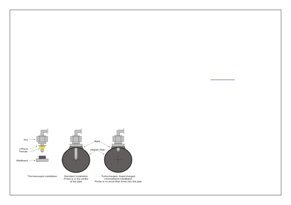
EGT Weld- In Sensor Installation Notes
When installing the Thermocouple probes into your headers please note the following:
•
For accurate temperature readings the placement of the weldment should be as close
to the header flange as practical up to 100mm from the flange is acceptable.
•
All weldments should be mounted in a position consistent on all pipes. It is very
important that they are all equidistant from the flange.
•
The ideal depth for the thermocouple probes in installations other than turbocharged or
any supercharged nitromethane applications, is to have the probe located in the centre
of the pipe.
•
The ideal depth for the thermocouple probes in turbocharged or supercharged
nitromethane fueled engines should be no more than 6mm into the pipe
EGT Weld- In Sensor Installation
1.
Select the header tube in which you wish to mount the probe
2.
Select the sensor location point on the pipe.
3.
Once the position is located, drill a 5/16 inch diameter hole in the header tube
4.
Remove the plastic protective tip from the thermocouple probe
5.
Center the weld-in weldment around the hole and weld to the header pipe a full 360
degrees
6.
Install the compression cap and ferrule on the welded base and bring up finger tight
7.
Measure the distance from the exposed tip, up the hot leg of the sensor that's equal to
the height of the compression fitting plus the immersion depth that the sensor will extend
into the exhaust stream. Mark that length using a marker or pencil
8.
Insert the thermocouple probe through the installed mounting hardware until the mark
touches the top of the cap and tighten the compression nut using a 9/16 inch spanner.
Make sure sensor transition and spring is at a 90 degree angle to the exhaust pipe, if
room permits. This will position the sensor tip correctly in the exhaust stream
Figure 4 – Thermocouple Installation
Haltech Thermocouple Amplifier
Quick Start Guide
Congratulations on purchasing a Haltech Thermocouple Amplifier.
This Plug and Play product allows the user the ability to increase the functionality
of their Haltech ECU by using the Haltech CAN system which is fitted to all
Platinum Series ECU's.
The Thermocouple Amplifier Box makes available multiple temperature inputs for
monitoring, tuning and logging.
This quick start guide will walk you through installation of the Haltech Thermocouple
Amplifier into a vehicle. This guide is accompanied by the full service manual located
on the software CD provided with the ECU that you or your tuner will need to refer to
before completing your installation and configuration. The Manual can also be
downloaded from the Haltech website
Included in Haltech Thermocouple Amplifier Kit – TCA2
•
Haltech 2 Channel Thermocouple Amplifier Box
•
Haltech CAN Cable Direct Connection Black 600mm
•
Quick start guide
•
Haltech Sticker
Included in Haltech Thermocouple Amplifier Kit – TCA4
•
Haltech 4 Channel Thermocouple Amplifier Box
•
Haltech CAN Cable Direct Connection Black 600mm
•
Quick start guide
•
Haltech Sticker
Optional Accessories ( Sold Separately )
•
Thermocouple Probes ( Please contact Haltech for probe sets available )
•
TCA – Flying Lead Auxiliary Harness ( HT049940 )
•
TCA – Plug and Pin Set ( HT030006 )
•
CAN Cable Hub Connection White, available in various sizes 75mm up to 3600mm
( Please contact Haltech for sizes and prices )
•
CAN Cable Direct Connection Black, available in various sizes 75mm up to 3600mm
( Please contact Haltech for sizes and prices )