Installation (continued), Drain valve connection, Permeate line plumbing – A.J. Antunes & Co UFL-440 9700475 User Manual
Page 12
UFL-420/440 WATER FILTRATION SYSTEM
12
P/N 1011055 Rev. F 12/13
INSTALLATION (continued)
Drain Valve Connection
The drain hose is for flushing particle buildup out of the
system during self cleaning.
1. Cut a length of the provided 20-foot coil of braided
tubing so it reaches the drain from the Drain
Valve.
2. Connect one end of the hose to the Drain Valve
and secure it with a provided Worm Clamp (Figure
4).
3. Direct the other end of the hose to the drain.
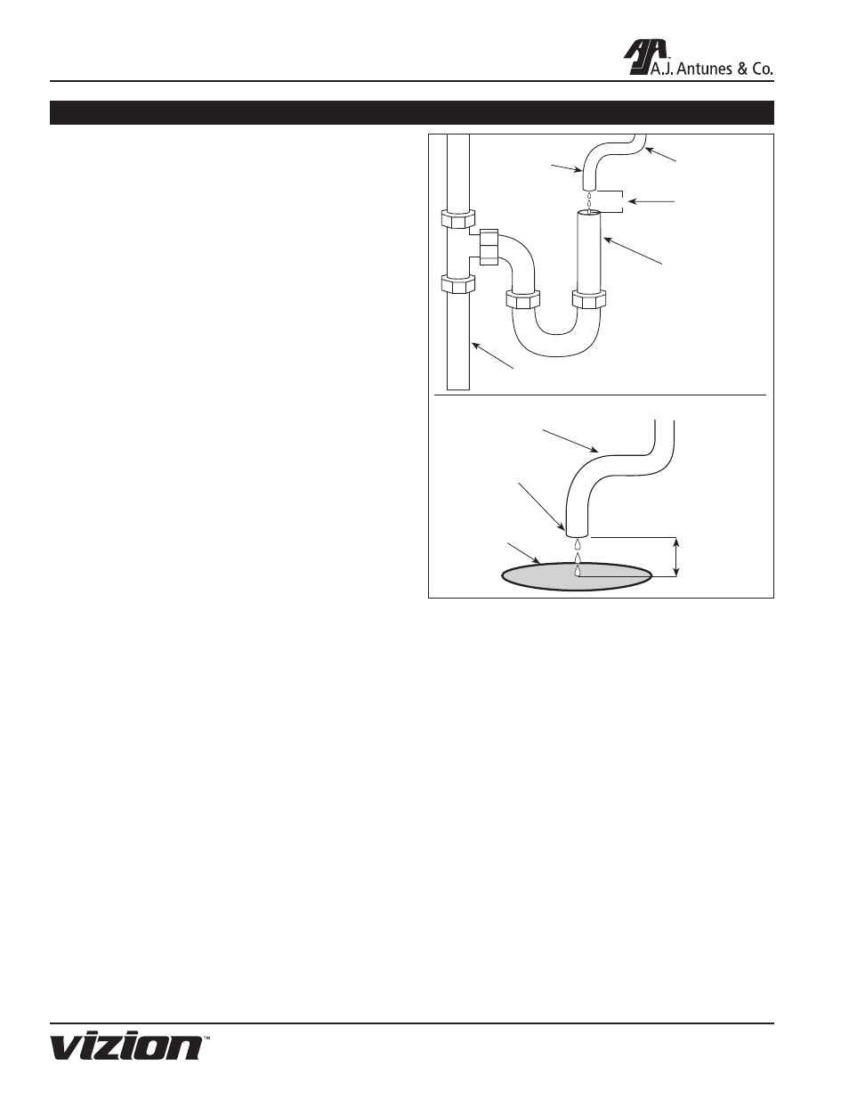
When connecting the drain hose, pay attention to the
following guidelines:
• The drain line plumbing must be able support the
flow rate whenever the system flushes. This flow
rate is dependent on the inlet water pressure, inlet
pipe size, and system.
• The drain line leading out of the system must be
as short as possible and slope downwards without
any kinks or loops.
• The drain line plumbing must be position and
secured at least 2 inches above the drain (Figure
4). This air gap protects the system from contami-
nation in the event of a backed-up drain.
• The drain used must not be blocked or restricted.
• The drain used must be as large or larger than
the drain line plumbing.
Permeate Line Plumbing
To ensure the highest quality and safest water, it is
recommended that a check valve (to prevent backflow)
be installed in the water line after the permeate connec-
tion. This will help prevent possible contamination of
the filter system due to other equipment downstream.
The check valve (not supplied) should be mounted
close to the system outlet, and sized properly for the
plumbing line. Check with local codes for the proper
specification.
A shutoff valve (not supplied) should be installed in the
filtered water line leading from the system. The valve
should be mounted close to the system outlet and sized
properly for the plumbing line. This valve will allow for
easier servicing and future cartridge replacement.
Figure 4. Proper Drain Plumbing
2” (5.1 cm)
minimum
2” (5.1 cm)
minimum
Floor
Drain
Secure
End
Drain Line
from System
Drain Line
from System
Secure
End
Drain
Standpipe