Installation, Description of the appliance, Positioning – Indesit VIX-644-C-E User Manual
Page 3
3
GB
Description of the appliance
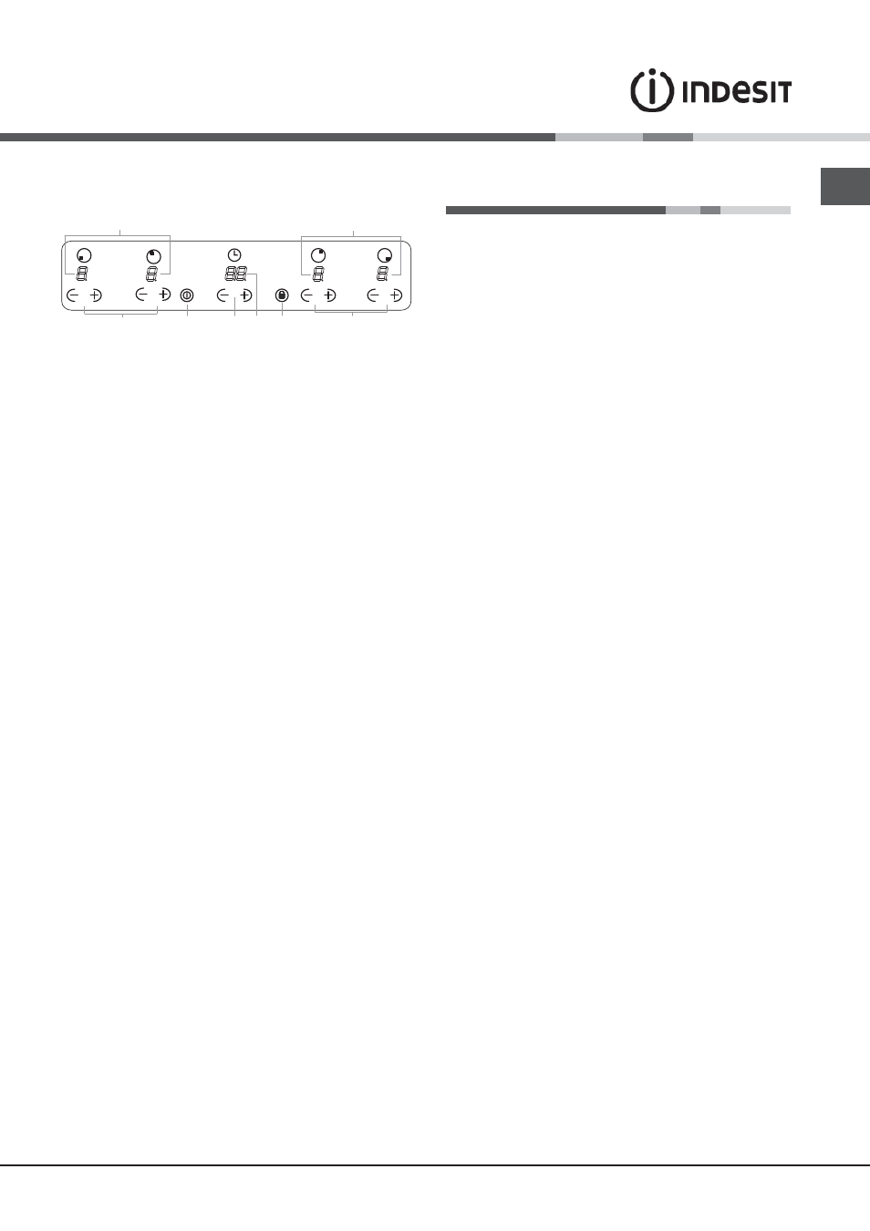
Control panel
Installation
!
Before operating your new appliance please read
this instruction booklet carefully. It contains important
information concerning the safe operation, installation
and maintenance of the appliance.
!
Please keep these operating instructions for future
reference. Pass them on to any new owners of the
appliance.
Positioning
!
Keep all packaging material out of the reach of children.
It may present a choking or suffocation hazard (see
Precautions and tips
).
!
The appliance must be installed by a qualified
professional in accordance with the instructions provided.
Incorrect installation may cause harm to people and
animals or may damage property.
Built-in appliance
Use a suitable cabinet to ensure that the appliance
functions properly.
• The supporting surface must be heat-resistant up to a
temperature of approximately 100°C.
• If the appliance is to be installed above an oven,
the oven must be equipped with a forced ventilation
cooling system.
• Avoid installing the hob above a dishwasher:
if this cannot be avoided, place a waterproof
separation device between the two appliances.
Ventilation
To allow adequate ventilation and to avoid overheating of the
surrounding surfaces the hob should be positioned as follows:
• At a minimum distance of 40 mm from the back panel
or any other vertical surfaces.
• So that a minimum distance of 20 mm is maintained
between the installation cavity and the cabinet
underneath.
• Kitchen cabinets adjacent to the appliance and taller
than the top of the hob must be at least 450 mm from
the edge of the hob.
Fixing
The appliance must be installed
on a perfectly level
supporting surface. Any deformities caused by improper
fixing could affect the features and operation of the hob.
The thickness of the supporting surface
should be taken
into account when choosing
the length of the screws for
the fixing hooks:
• 3,5 mm thick: 9,5 mm screws
The control panel described in this manual is only a representative
example: it may not exactly match the panelon your appliance.
When using the touch control pannel panel:
•
Do not use gloves
•
Use a clean finger
•
Touch the glass smoothly
1 INCREASE(+)/REDUCE(-) POWER button - controls
the power level on every individual cooking zone
2 INCREASE (+)/ REDUCE(-) TIME button -controls the
time of cooking on the cooking zones.
3 COOKING ZONE POWER displays -show the power
level selected for every individual cooking zone
4 ON/OFF button switches the appliance on and off.
5 CONTROL PANEL LOCK button prevents accidental
changes to the hob settings and shows the control
panel has been locked
6. .TIMER display -shows the cookig time selected .
! For detailed information on the control panel functions
refer to “Start-up and use” section.
! This product complies with the requirements of the
latest European Directive on the limitation of power
c o n s u m p t i o n o f t h e s t a n d b y m o d e .
If no operations are carried out for a period of 2
minutes, after the residual heat indicator lights turn
off and the fan stops (if present), the appliance
a u t o m a t i c a l l y s w i t c h e s t o t h e . o f f m o d e . .
The appliance resumes the operating mode once the
ON/OFF button is pressed.
! Depending on the number of heaters/cooking zones on
the hob the COOKING ZONE SELECTED INDICATORS
may vary between 3 and 4
2
5
4
1
6
1
3
3