Indesit KP902GX User Manual
Page 4
4
GB
Make sure that the hose complies with current
national legislation. The internal diameter of the hose
must measure: 8 mm for liquid gas supply; 13 mm for
methane gas supply.
Once the connection has been performed, make sure
that the hose:
• Does not come into contact with any parts that
reach temperatures of over 50°C.
• Is not subject to any pulling or twisting forces and
that it is not kinked or bent.
• Does not come into contact with blades, sharp
corners or moving parts and that it is not
compressed.
• Is easy to inspect along its whole length so that its
condition may be checked.
• Is shorter than 1500 mm.
• Fits firmly into place at both ends, where it will be
fixed using clamps that comply with current
regulations.
! If one or more of these conditions is not fulfilled or
if the cooker must be installed according to the
conditions listed for class 2 - subclass 1 appliances
(installed between two cupboards), the flexible steel
hose must be used instead (see below).
Connecting a flexible jointless stainless steel pipe to
a threaded attachment
Make sure that the hose and gaskets comply with
current national legislation.
To begin using the hose, remove the hose holder on
the appliance (the gas supply inlet on the appliance
is a cylindrical threaded 1/2 gas male attachment).
! Perform the connection in such a way that the hose
length does not exceed a maximum of 2 metres,
making sure that the hose is not compressed and
does not come into contact with moving parts.
Checking the tightness of the connection
When the installation process is complete, check
the hose fittings for leaks using a soapy solution.
Never use a flame.
Adapting to different types of gas
It is possible to adapt the appliance to a type of gas
other than the default type (this is indicated on the
rating label on the cover).
Adapting the hob
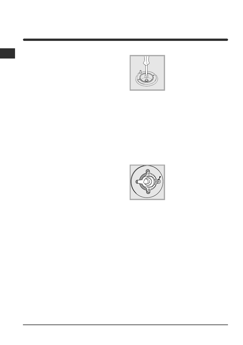
Replacing the nozzles for the
hob burners:
1. Remove the hob grids and
slide the burners off their seats.
2. Unscrew the nozzles using a
7 mm socket spanner (see
figure), and replace them with
nozzles suited to the new type of
gas (see Burner and nozzle specifications table).
3. Replace all the components by following the above
instructions in reverse.
Adjusting the hob burners minimum setting:
1. Turn the tap to the minimum position.
2. Remove the knob and adjust the regulatory screw,
which is positioned inside or next to the tap pin, until
the flame is small but steady.
If the appliance is connected to a liquid gas supply,
the regulatory screw must be fastened as tightly as
possible:
3. While the burner is alight, quickly change the position of
the knob from minimum to maximum and vice versa
several times, checking that the flame is not extinguished.
The hob burners do not require primary air adjustment.
After adjusting the appliance so it may be used with a
different type of gas, replace the old rating label with a
new one that corresponds to the new type of gas (these
labels are available from Authorised Technical Assistance
Centres).
Should the gas pressure used be different (or vary
slightly) from the recommended pressure, a suitable
pressure regulator must be fitted to the inlet hose in
accordance with current national regulations relating
to regulators for channelled gas.