Indesit KP9F11SX-G User Manual
Page 3
GB
3
compliance with the norms. The air flow from the
adjoining room to the one to be ventilated may pass
freely through permanent apertures with a cross
section at least equal to that indicated above. These
apertures may also be obtained by increasing the gap
between the door and the floor. If an electric fan is
used for extracting the combustion products, the
ventilation aperture must be increased in relation to its
maximum performance. The electric fan should have a
sufficient capacity to guarantee an hourly exchange of
air equal to 3 ÷ 5 times the volume of the kitchen.
Prolonged, intensive use of the appliance may require
extra ventilation, e.g. an open window or a more
efficient ventilation system by increasing the extraction
power of the electric fan if installed. Liquid petroleum
gas descends towards the floor as it is heavier than
air. Apertures in the outside walls in rooms containing
LPG cylinders should therefore be at floor level, in
order to allow any gas from leaks to be expelled. Do
not store LPG cylinders (even when empty) in
basements or rooms below ground level; it is
advisable to keep only the cylinder in use in the room
at any one time and connected far from heat sources
which could raise its temperature to above 50 °C.
Gas supply
Check that the appliance is set for the type of gas
available and then connect it to the mains gas
piping or the gas cylinder in compliance with the
applicable norms in force.
This appliance is designed and set to work with the
gas indicated on the label situated on the actual
hob. If the gas supply is different from the type for
which the appliance has been set, replace the
corresponding nozzles (provided), following the
instructions given in the paragraph "Adaptation to
different types of gas".
For trouble-free operation, suitable use of energy
and a longer life cycle for the appliance, make sure
that the supply pressure complies with the values
indicated in table 1 "Burner and nozzle
specifications", otherwise install a special pressure
regulator on the supply pipe in compliance with
current standards and regulations.
Connect in such a way that the appliance is
subjected to no strain whatsoever.
Either a rigid metal pipe
with fittings in
compliance with the
standards in force must
be used for connecting
to the nipple union
(threaded ½"G male
fitting) situated at the
rear of the appliance to
the right, or flexible steel
pipe in compliance with
the standards in force, which must not exceed 2000
mm in length.
Should it be necessary to turn the fitting, the gasket
(supplied with the appliance) must be replaced. Upon
completion of installation, check the gas circuit, the
internal connections and the taps for leaks using a
soapy solution (never a flame).
Also check that the connecting pipe cannot come into
contact with moving parts which could damage or
crush it.
Make sure that the natural gas pipe is adequate for a
sufficient supply to the appliance when all the burners
are lit Important: A pressure regulator, in compliance
with the standards in force, must be inserted when
connecting to a liquid gas supply (in a cylinder).
Adapting to different types of gas
To adapt the hob to a different type of gas from the
factory-set one (indicated on the rating plate at the top
of the hood or on the packaging), the burner nozzles
should be replaced as follows:
Remove the hob grids and slide the burners off their
seats.
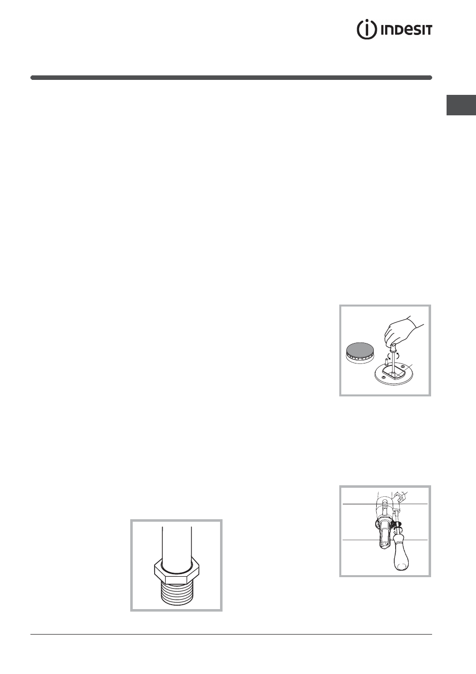
Unscrew the nozzles
(see figure), using a 7
mm socket spanner
and replace them with
nozzles for the new
type of gas (see table
1 "Burner and nozzle
characteristics").
Reassemble the parts
following the above
procedure in the
reverse order.
On completing the operation, replace the old rating
label with the one showing the new type of gas; the
sticker is available from our Service Centres.
Adjusting the primary air of the burners The primary
air of the burners does not need to be adjusted.
Adjusting the low flame
Turn the tap to the low flame position;
Remove the knob and
turn the adjusting
screw, situated to the
right of the tap (see
figure) until you obtain
a regular small flame,
using a screwdriver
(loosening the screw
increases the height
of the flame,
tightening decreases
it).
N.B.: In the case of liquid gas, the regulation
screw must be screwed in all the way.
A