Chapter 3: option selection, Figure 3-1: option selection map, Filter response switch – Access PCI-IDI-XX User Manual
Page 11: Manual pci-idi-xx series
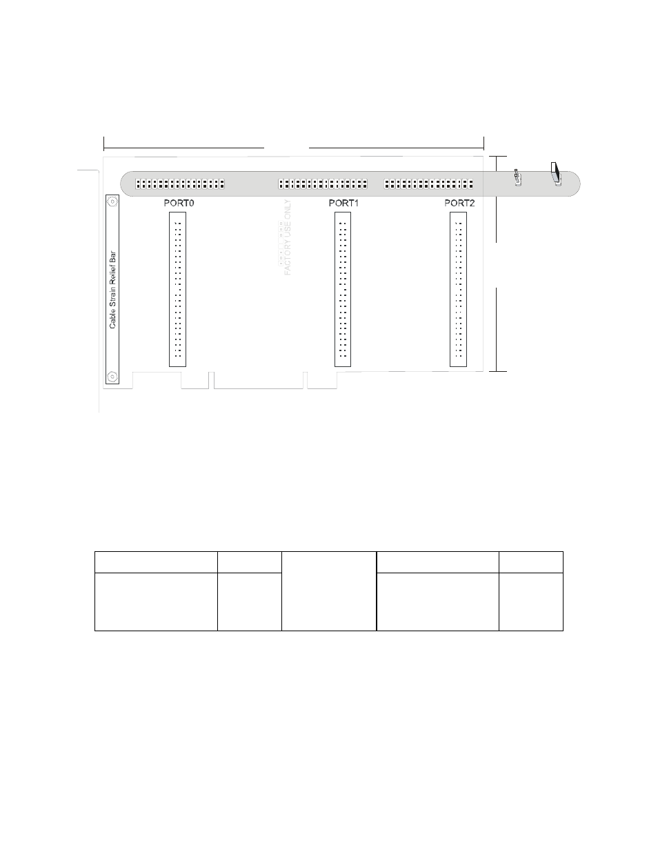
Chapter 3: Option Selection
Each channel has a jumper configurable filter option.
3.
90
"
6.90"
NO FILTER
FILTER
FL
T
0
FL
T1
5
FL
T1
6
FL
T
3
1
FL
T3
2
FL
T4
7
Figure 3-1: Option Selection Map
Filter Response Switch
Jumpers are used to select input filtering on a channel-by-channel basis (see Figure 3-1). When jumper
FLT0 is installed, filtering is introduced for input bit 0, FLT1 for bit 1, and so on. The tables below describe
filtering for Port 0. Ports 1 and 2 follow the same pattern with Port 1 having FLT16-31 (Bits 16-31) and
Port 2 having FLT32-47 (Bits 32-47). Filtering provides a slower response for DC signals as described
previously and must be used when AC inputs are applied.
JUMPER SELECTION
Bit Filtered
JUMPER SELECTION
Bit Filtered
FLT-0
FLT-1
FLT-2
...
Bit 0
Bit 1
Bit 2
...
FLT-8
FLT-9
FLT-10
...
Bit 8
Bit 9
Bit 10
...
Manual PCI-IDI-XX Series
11