Microstep selection (sw1 settings), Setting the output current – Anaheim DPG10003-01 User Manual
Page 6
User’s Guide # L010167
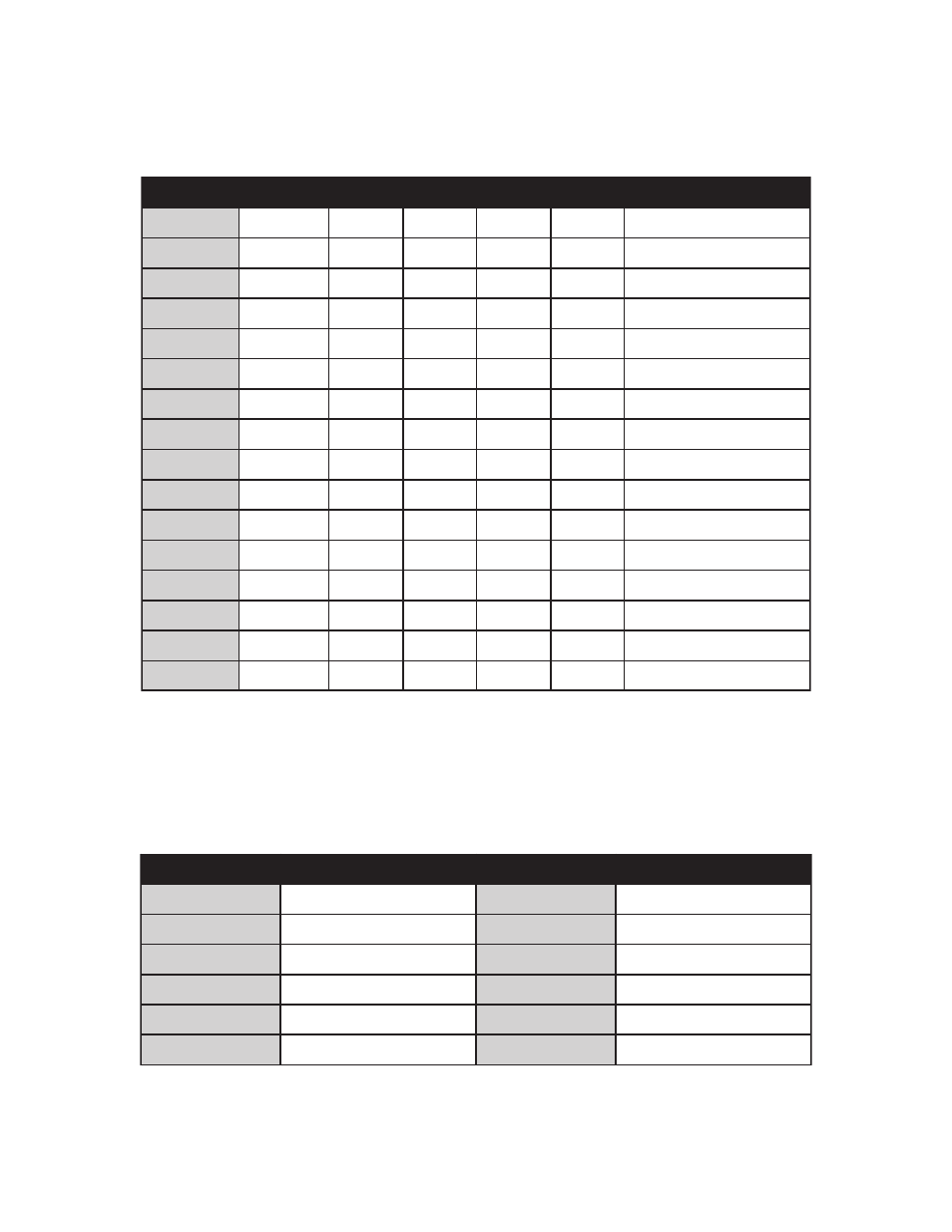
Microstep Selection (SW1 Settings)
Switches 2, 3 and 4, of the DIP switch select the number of microsteps per step. Table 7 shows the
standard resolution values along with the associated positions for the select switches. The standard wave-
forms are sinusoidal.
Setting the Output Current
The output current on the MBC10641 is set by an onboard potentiometer. This potentiometer determines
the per phase peak output current of the driver. The relationship between the output current and the
potentiometer value is as follows:
Table 7: Potentiometer values with respect to the output current
Refer to Table 5 for specific motor current settings.
Table 6: Microstep Selection on Switch 1.
n
o
i
t
u
l
o
s
e
R
v
e
R
/
s
p
e
t
S
1
t
c
e
l
e
S
2
t
c
e
l
e
S
3
t
c
e
l
e
S
4
t
c
e
l
e
S
t
n
e
r
r
u
C
e
c
u
d
e
R
o
t
u
A
1
0
0
2
F
F
O
N
O
N
O
N
O
d
e
l
b
a
s
i
D
2
0
0
4
F
F
O
N
O
N
O
F
F
O
d
e
l
b
a
s
i
D
5
0
0
0
1
F
F
O
N
O
F
F
O
N
O
d
e
l
b
a
s
i
D
8
0
0
6
1
F
F
O
N
O
F
F
O
F
F
O
d
e
l
b
a
s
i
D
0
1
0
0
0
2
F
F
O
F
F
O
N
O
N
O
d
e
l
b
a
s
i
D
6
1
0
0
2
3
F
F
O
F
F
O
N
O
F
F
O
d
e
l
b
a
s
i
D
2
3
0
0
4
6
F
F
O
F
F
O
F
F
O
N
O
d
e
l
b
a
s
i
D
4
6
0
0
8
2
1
F
F
O
F
F
O
F
F
O
F
F
O
d
e
l
b
a
s
i
D
1
0
0
2
N
O
N
O
N
O
N
O
d
e
l
b
a
n
E
2
0
0
4
N
O
N
O
N
O
F
F
O
d
e
l
b
a
n
E
5
0
0
0
1
N
O
N
O
F
F
O
N
O
d
e
l
b
a
n
E
8
0
0
6
1
N
O
N
O
F
F
O
F
F
O
d
e
l
b
a
n
E
0
1
0
0
0
2
N
O
F
F
O
N
O
N
O
d
e
l
b
a
n
E
6
1
0
0
2
3
N
O
F
F
O
N
O
F
F
O
d
e
l
b
a
n
E
2
3
0
0
4
6
N
O
F
F
O
F
F
O
N
O
d
e
l
b
a
n
E
4
6
0
0
8
2
1
N
O
F
F
O
F
F
O
F
F
O
d
e
l
b
a
n
E
t
n
e
r
r
u
C
k
a
e
P
g
n
i
t
t
e
S
r
e
t
e
m
o
i
t
n
e
t
o
P
t
n
e
r
r
u
C
k
a
e
P
g
n
i
t
t
e
S
r
e
t
e
m
o
i
t
n
e
t
o
P
A
5
.
1
%
0
A
0
.
7
%
0
6
A
3
.
2
%
0
1
A
9
.
7
%
0
7
A
1
.
3
%
0
2
A
7
.
8
%
0
8
A
0
.
4
%
0
3
A
6
.
9
%
0
9
A
0
.
5
%
0
4
A
0
1
%
0
0
1
A
0
.
6
%
0
5
-
-
-
-