2 bridge mode, Input connector, Channel 2 channel 1 – Nilfisk-ALTO DPA6000 User Manual
Page 17: Channel 1, Channel 2, Balanced
RS485 IN
RS485 OUT
RS232
SERIAL PROT
CH1
BALANCED
INPUT
PARALLEL
OUTPUT
CH2
BALANCED
INPUT
PARALLEL
OUTPUT
SERIAL
MODEL
1+
1-
POS
NEG
BRIDGE
MONO
2+
2-
POS
NEG
1+
2+
POS
NEG
1+
1-
POS
NEG
INPUT
INPUT
TIP/PIN 2
RING/PIN 3
SLEEVE/PIN 1
TIP/PIN 2
RING/PIN 3
SLEEVE/PIN 1
INPUT
INPUT
BREAKER
Apparaten skall anslutas
till jordat uttag nar den
ansluts till ett natverk
MODE
BRIDGE
STEREO
LIMITER
OFF
ON
2
1
3
2
1
3
2
1
2
1
16
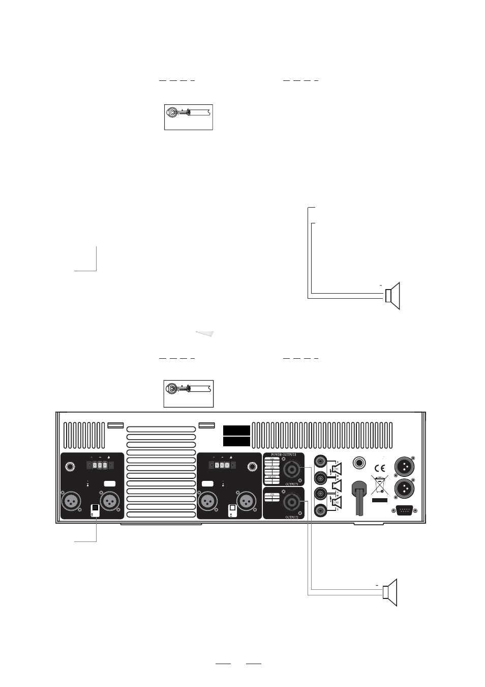
9.2 Bridge Mode
In this mode, the signal input into channel 1 will be output from the bridged end, on the other hand, the output level
control of channel 2 should be turn down to smallest (turn the volume control at counterclockwise). Only the volume
control of channel 1 is used to control the volume of whole system.
MODE
this button
Release
MODE
this button
Release
MODE
this button
Release
Channel 1
+
Channel 2
+
Channel 2
Channel 1
Balanced
1
2
3
GND
INPUT
Input Connector
Input Connector
1
2
3
GND
INPUT
Balanced
Input Connector
Input Connector