9" (22.9 cm) ventilador multidireccional, Manual de instrucciones de operación y partes, Lea y guarde estas instrucciones – Air King 4C523K User Manual
Page 2: Descripción, Especificaciones, Información general sobre seguridad, Mantenimiento, Replacement parts list assembly, Operation
R
LEA Y GUARDE ESTAS INSTRUCCIONES
LÉALAS CUIDADOSAMENTE ANTES DE INTENTAR ARMAR, INSTALAR, OPERAR O DAR MANTENIMIENTO AL PRODUCTO
DESCRITO. PROTÉJASE A SÍ MISMO Y A LOS DEMÁS OBSERVANDO TODA LA INFORMACIÓN SOBRE SEGURIDAD. ¡NO
SEGUIR LAS INSTRUCCIONES PODRÍA RESULTAR EN LESIONES PERSONALES Y/O DAÑOS A LA PROPIEDAD!
GUARDE LAS INSTRUCCIONES PARA REFERENCIAS FUTURAS.
DESCRIPCIÓN
El ventilador oscilante AirKing de 9" (22.9 cm) es de operación silenciosa y
tiene una unidad giratoria de 3 paletas. El ventilador tiene un motor
permanentemente lubricado con un cordón eléctrico de 6 pies (1.8 m) 18/3.
3
MANUAL DE INSTRUCCIONES DE OPERACIÓN Y PARTES
MODELO 4C523K/9154K
9" (22.9 cm) VENTILADOR
MULTIDIRECCIONAL
2084020A
Rev. F 9/00
HELICE
MOTOR
TUERCA DE
PLÁSTICO
REJILLA TRASERA
REJILLA
DELANTERA
SOPORTE DE
SUJETADORES
SUJETADOR
DE REJILLA
.
GANCHO
CONTROL DE OSCILACIÓN
TORNILLO DE
ELEVACIÓN
BOTÓN DEL
INTERRUPTOR
a.
b.
ESPECIFICACIONES
Motor .................................................. 120V, 60Hz
Tamaño de paletas ............................ 9" (22.9 cm)
Velocidades ....................................... 2
Control ............................................... Conjuntor rotatorio
Distribución del lujo de aire ................ 90
°
Aprobaciones ..................................... Catalogación UL. El protector
de malla cerrada del ventilador
satisface las normas OSHA.
MODELO
4C523K/9154K
VELOCIDAD
ALTA
BAJA
CFM
1205
906
M
3
/s
.57
.43
RPM
2175
1644
Amps
.55
.32
Watts
32
22
dB A
41
34
INFORMACIÓN GENERAL SOBRE SEGURIDAD
1. Cerciórese de que la fuente de electricidad se adapte a los requerimientos
eléctricos del ventilador.
2. El cordón eléctrico está equipado con una clavija a tierra de tres espigas
que tiene que ser enchufada a un receptáculo del mismo diseño. Bajo
ninguna circunstancia deberá cortarse la espiga a tierra de la clavija. De
existir un receptáculo de pared de dos espigas, deberá reemplazarse por
uno de tres espigas debidamente puesto a tierra e instalado de conformidad
con el Código Nacional de Electricidad y todos los códigos y ordenanzas
locales aplicables. El trabajo deberá hacerlo un electricista calificado,
utilizando exclusivamente alambre de cobre.
ADVERTENCIA: NO SE RECOMIENDA EL USO DE UN ADAPTADOR DE
TRES A DOS ESPIGAS. LA CONEXIÓN INDEBIDA PODRÍA CREAR EL
RIESGO DE SER ELECTROCUTADO. EL USO DE TALES
ADAPTADORES NO ESTÁ PERMITIDO EN CANADÁ.
3. Siempre que sea posible, evite el uso de extensiones eléctricas. Si tienen
que usarse, minimice el riesgo de sobrecalentamiento asegurándose de
que sean de catalogación UL y del calibre y la longitud adecuadas. Nunca
use una sola extensión para operar más de un ventilador.
4. No introduzca los dedos ni objetos extraños en el ventilador. No obstruya
ni manipule indebidamente el ventilador mientras esté en operación. No
toque el ventilador mientras esté en operación ni inmediatamente después
de haberlo apagado, ya que ciertas partes podrían estar lo suficientemente
calientes como para causar una lesión.
5. Desenchufe el cordón eléctrico antes de instalar o dar servicio al
ventilador.
ADVERTENCIA: NO DEPENDA DEL INTERRUPTOR DE ENCENDIDO Y
APAGADO COMO EL ÚNICO MEDIO PARA INTERRUMPIR LA
ALIMENTACIÓN ELÉCTRICA CUANDO INSTALE O DÉ SERVICIO AL
VENTILADOR. SIEMPRE DESENCHUFE EL CORDÓN ELÉCTRICO.
6. Este ventilador es para uso general EXCLUSIVAMENTE. NO deberá
usarse en localidades potencialmente peligrosas tales como atmósferas
inflamables, explosivas, cargadas de gases o húmedas.
ADVERTENCIA: PARA REDUCIR EL RIESGO DE INCENDIOS O
DESCARGAS ELÉCTRICAS, NO USE ESTE VENTILADOR CON NINGÚN
DISPOSITIVO DE CONTROL DE VELOCIDAD DE ESTADO SÓLIDO.
7. Asegúrese de que el ventilador esté sobre una superficie estable al estar
en funcionamiento, para evitar toda riesgo de que se voltee.
8. NO utilice el ventilador en una ventana, ya que la lluvia podría crear un
peligro eléctrico.
9. Vuelva a armar completamente el ventilador, de acuerdo con las
instrucciones, antes de volver a conectarlo a la alimentación eléctrica.
MANTENIMIENTO
ADVERTENCIA: DESCONECTE SIEMPRE EL CORDÓN ANTES DE
INTENTAR REALIZAR CUALQUIER FUNCIÓN DE SERVICIO.
LIMPIEZA:
Use un trapo y una solución de jabón suave, tal como
detergente líquido para lavar trastes.
ADVERTENCIA: No use gasolina, bencina, diluyente de pintura ni
limpiadores fuertes en aerosol, ya que éstos dañarán el ventilador.
ALMACENAMIENTO
: Cuando no lo utilice, mantenga el aparato en un
lugar limpio y seco.
EL MOTOR HA SIDO PERMANENTEMENTE LUBRICADO.
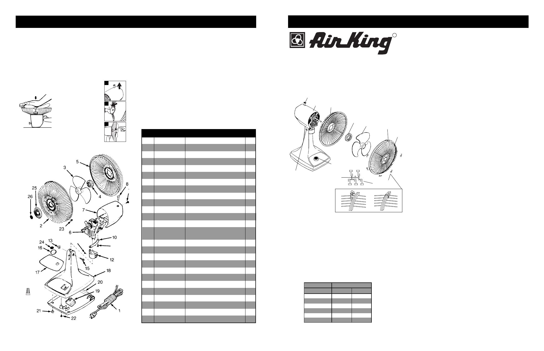
1
2050009AW
Cord Set
1
2
2096045
Front Grill
1
3
2010004
Blade
1
4
2010350
Plastic Nut
1
5
2096050
Rear Grill
1
6
2030056G
Motor
1
7
2010619
Motor Cover
1
8
2010119
Oscillation Knob
1
10
2010279
Link
1
11
2090068
Screw #6 x 1/2" LH/H.W.H.
1
12
2010260
Neck
1
13
2091133
Hex Nut 1/4 x 20
1
14
2090529
Wire Nut A-O
1
15
2090199
Elevation Screw
1/4 - 20 x 1" PPH
1
16
2010104
Switch Knob
1
17
2065412
Stand Ornament
1
18
2010524
Stand
1
19
2057065
Rotary Switch
1
20
2010281
Bottom Plate
1
21
2010403A
Rubber Foot (4 used)
4
22
2090038
Screw #8 x 9/16 PPH
2
23
2010354
Plastic Grill Clips
5
24
2066506G
Switch Knob Insert
1
25
2010241A
Grill Ornament
1
26
2070024G
Bullseye (AirKing)
1
27
2090073
Screw #6 x 1/2" AB
1
REPLACEMENT PARTS LIST
ASSEMBLY
(Assembly Illustration - Page 1)
1. Place REAR GRILL on MOTOR. Align holes in REAR GRILL with pins
on MOTOR.
2. Fasten REAR GRILL with PLASTIC NUT.
3. To avoid damaging BLADE, install by pushing firmly in CENTER HUB,
onto MOTOR SHAFT. (Follow steps below)
11
2
14-
MODEL 4C523K/9154K
2084020A
4. Place HOOK on FRONT GRILL over top center wire on REAR GRILL.
Align GRILLS.
5. With a twist, gently remove GRILL CLIPS from HOLDER and position
evenly around fan. Attach clips by snapping tail of CLIP over round wire
on REAR GRILL. Snap body of CLIP around flat wires of both GRILLS.
(Figures a and b, Page 1)
OPERATION
1. SPEEDS: The speed is controlled by the rotary switch located on the
fan stand.
2. OSCILLATION: Push down on the knob on the motor cover to start fan
oscillation. Pull up on the knob to stop fan oscillation.
3. ANGLE ADJUSTMENT: The angle of the upper fan assembly may be
changed by first loosening the elevation screw. Position the upper
assembly to the desired angle and lock in place by retightening elevation
screw.
Key
Part No.
Description
Qty.
22
a) Pull oscillating knob up to
disengage oscillating
mechanism.
b) Using a blunt object, such
as a screwdriver handle,
gently tap on the front of
the blade hub. DO NOT
tap blade hub straight
back into the motor.
c) Spin blade by hand. If
blade does not spin freely
repeat previous step until
blade does spin freely.
CAUTION: At no time
should you turn the fan on
without grills being
securely attached.
TAP
HUB
SPIN
UP
1
2
3
a
b
c
Center
HUB
Rev. F 9/00
27