Diagram of aquastar 125fx – AquaStar 125FX LP User Manual
Page 19
19
6 720 606 601
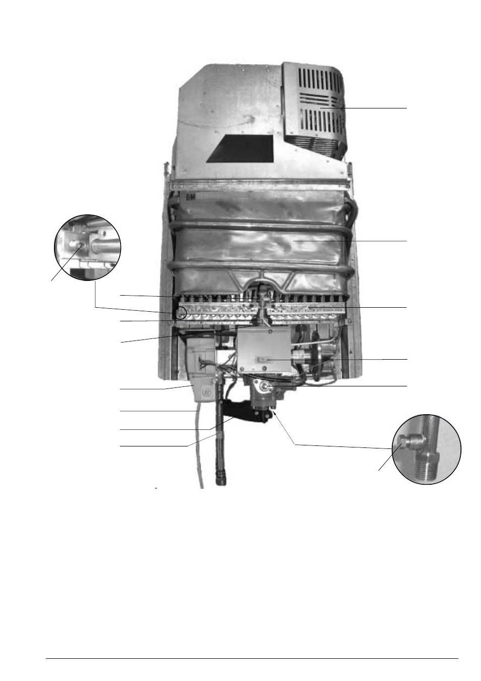
Fig. 15 -
Diagram of AquaStar 125FX
1.
Heat exchanger
2.
Pilot assembly
3.
Burner manifold gas
pressure test nipple
4.
Main gas burner
5.
Pilot gas tubing
6.
Gas valve
7.
electric control box
8.
Power cord
9.
on/off switch
10.
Temperature adjustment selector
11.
Microswitch
12.
Gas inlet gas pressure test nipple
13.
Exhaust Fan
14.
Flexible hot outlet
5
11
1
4
9
10
12
2
6
8
7
13
3
14
6 720 606 601-12.1AL
This manual is related to the following products: