Sensor mounting and installation – Campbell Scientific SR50-L CSC Ultrasonic Distance Sensor User Manual
Page 25
SR50 Sonic Ranging Sensor
19
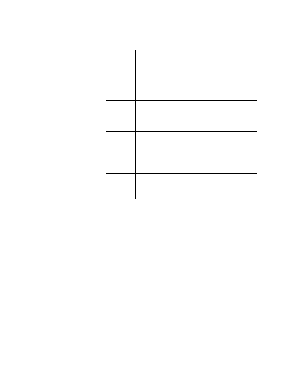
TABLE 2. Address Jumper Settings for Pulse Train and ASCII Outputs
ADDRESS
OUTPUT FORMAT
0
Pulse Train 1000 Hz 2.5mm/Pulse
1
Pulse Train 100 Hz 2.5mm/Pulse
2
Pulse Train 1000 Hz 1cm/Pulse
3
Pulse Train 100 Hz 1cm/Pulse
4
Pulse Train 1000 Hz 0.1 inch/Pulse
5
Pulse Train 100 Hz 0.1 inch/Pulse
6
RS-232 1200 BAUD (3 Targets (Meters) with Quality
Numbers)
7
RS-232 300 BAUD (3 Targets (Meters) with Quality Numbers)
8
TTL 1200 BAUD (3 Targets (Meters) with Quality Numbers)
9
TTL 300 BAUD (3 Targets (Meters) with Quality Numbers)
10
RS-232 1200 BAUD (First Target (Meters))
11
RS-232 300 BAUD (First Target (Meters))
12
TTL 1200 BAUD (First Target (Meters))
13
TTL 300 BAUD (First Target (Meters))
14
RS-232 9600 BAUD (Single Target (Meters))
15
Factory Test Mode
4. Sensor Mounting and Installation
When mounting the SR50, the sensor's beam angle needs to be considered (see
Figure 5). It is important to remember that the SR50 has a beam angle of
approximately 22 degrees. This means that no objects should obstruct the
intended target within this 22 degree beam. If an obstruction is within this
beam angle the SR50 may detect the unwanted object instead of the intended
target. By inserting a height value in Formula 2, a Clearance Radius in the
same measurement units as the height can be obtained.
(
)
radius
height
CONE
= 0.194 CONE
FORMULA 2. Clearance Radius