2 operational, 3 port configuration/connections – Campbell Scientific SDS122 Two-Way Serial Data Switch User Manual
Page 6
SDS-122 SERIAL DATA SWITCH
2
2.2 OPERATIONAL
TABLE 1. Current Consumption in Various Modes/Communication Activity
Mode
Activity
Current Drain
from Datalogger
Isolated
Quiescent (not communicating)
<75
µ
A
Isolated
Communicating
Up to 3mA
Non-Isolated
No RAD-SRM modem connected and with no
communication activity (quiescent)
<100
µ
A
Non-Isolated
RAD-SRM connected, waiting for call
2.5mA
Non-Isolated
RAD-SRM in comms. session but no communication
activity
9Ma
Non-Isolated
RAD-SRM communicating with PC208E or TCOM in
Monitor Mode
12mA
Non-Isolated
Jumper PL50 not fitted; RAD-SRM connected but no
communication activity. (This is the one-way, print-
enabled RAD-SRM mode.)
<100
µ
A
Normal Operating Temperature Range: -25
°
C to +50
°
C
For extended temperature range requirements please contact Campbell Scientific.
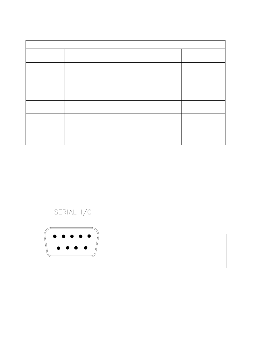
2.3 PORT CONFIGURATION/CONNECTIONS
The SDS-122 has one datalogger port, one
switched datalogger port, a 25-way switched
RS232 port and a control port.
Datalogger Port
FIGURE 2. Pin Positions for Datalogger
Port: 9-way Male ‘D’ Type Connector
The datalogger port (marked ‘LOGGER’ in
Figure 1) is a 9-way male ‘D’ type connector,
having the following pin configuration:
PIN
ABBREVIATION
I/O
1
+5V
2
0V
3
RING
O
4
RX
O
5
ME
I
6
SDE/PE I
7
CLK/HS
I
8
Not connected
9
TX
I
NOTE: When the datalogger is in
communication mode, pin 5 (ME –
Modem Enable) is held high. This line is
used by the SDS-122 to detect
communications and prevent switching to
the other port.
1 2 3 4 5
6 7 8 9